|

|
|
|
Gearbox Project. |
|
|
|
This section of the site is being devoted to the work to upgrade the drive train of Xtreme impaX to make it more competitive. The existing wheelchair motors are Chinese
made "Dynamics" and are very similar to the NPC R81 and R82 from NPC Robotics
www.npcrobotics.com and are to interchangeable with them. I got the Dynamics from a junkyard for only $20 the set so they were unbeatable value! The problem with
them is that they have an approximately 32:1 gear ratio so that unless you have large diameter wheels the bot is too slow in the arena. I mistakenly thought that wouldn't be much of a problem as we
were building a full body spinner (a la Phrizbee) but quickly found that in combat the ability to move quickly about the arena is vital for several reasons, firstly to avoid your opponent long enough
to spinup initially, secondly to be able to quickly take advantage of any mistakes your opponents make and lastly and very importantly, its very hard to look aggressive if your opponent can run circles
around you! This problem is very obvious in our fight
against Phrizbee at NCRSF III |
|
|
|
|
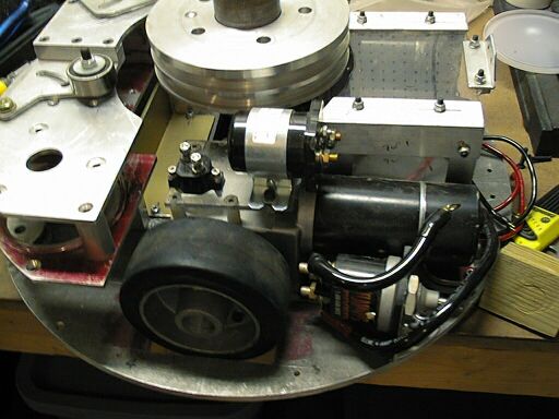
One of the existing motors can be seen in this picture of Xtreme impaX as at NCRSF II. They fit nicely into the low profile required by a full body spinner
and mount the entire drive train in one neat package. |
|
|
|
|
The new drive train needed to fit into the same or less space than the original, weigh less and provide at least 1HP per wheel and about 10MPH. To be able to check out
the alternatives I bought a copy of Enigma Industries Electric Drive Train Simulator
www.Enigmaindustries.com
and from that was able to work out that EV warriors or A-Packs with 10:1 gearing would give us what we needed. It also showed that a couple of 4lb 24v Battlepacks would be enough to power them for the time required. I spent a lot of time trying different layouts of gears, chains, timing belts and even worm gears but could not find one that would fit neatly and allow for the future replacement of the motors with something more exotic like Magmotors or similar. The cost of the upgrade looked like it was going to be excessive as I was having to get new axles, bearing supports and motor mounts etc.
I decided to look at what would be involved in perhaps regearing the original gearboxes to change the ratios. This proved to be virtually impossible because one of the secondary gears is machined from the
secondary shaft and the final gear is mounted on a spline. To regear the boxes would have required new primary and secondary shafts and as a last complication the worm gear was machined from the output
shaft of the motor itself! I raised the issue in a post to the Battlebots forum
http://forums.delphiforums.com/BattleBot_Tech/start and got some useful guidance from Rich Reid at NPC Robotics and he sent some pictures of some very
similar gearboxes he had where the motor shaft was not used as the worm gear and that would make it easier to mount a different motor. |
|
|
|
|
|
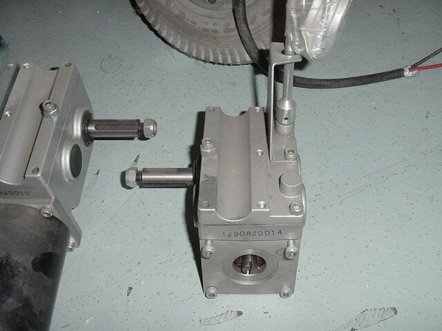
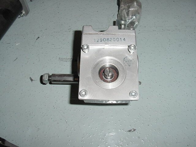
These two pictures from Rich show the MIT gearboxes he had. They had the most of the same mounting points as my Dynamics and the advantage that the
motor was a completely separate unit from the gearbox. This would resolve one problem but would do nothing to help with the overly low gearing. It then occurred to me that if I can't
change the ratio of the box the I need to increase the rpm of the input shaft by about 3X and I would get the output speed I needed. The easy way to do that is to use a motor that has a
very high RPMs to start with and a look through EDTS turned up the 24v DeWalt as an ideal candidate. |
|
|
|
|
|
|
|
|
|
The 24v DeWalt motors produce about 0.98HP at 24v and have a no load speed of about 22,000 RPM. By utilising the Dustin brush housing www.dcwaterjet.com
(no longer in Business) they can safely be run at 36v to produce over 2.2HP!EDTS indicated that in a heavyweight with 32:1
gearing they would give a speed in excess of 11MPH at 24v, just what was needed. I feel the boxes themselves are probably strong enough as they are considerably stronger than the standard DeWalt units but
are probably a lot less efficient but should still result in a big improvement over a standard wheelchair unit. Rich has been kind enough to send the MIT units to me for evaluation and I intend to
design an adapter set to suit. The prototype will be tested at NCRSF IV. These gearboxs are however not the same as those on the R81 and R82 which, like the dynamics, have the worm as part of the motor
shaft. These to could be adapted but would require a new worm shaft and bearing support as well as the DeWalt mount. We are going to try to contact the maker of the MIT units to see if further units
are available and at what cost. |
|
|
|
|
|
|
|
|
|
|
|
|
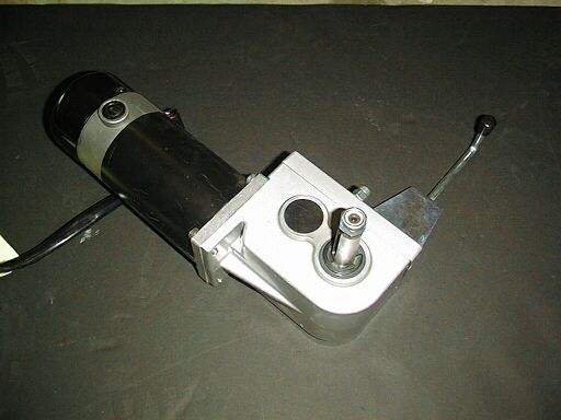
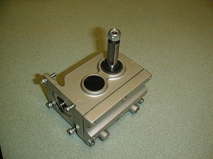
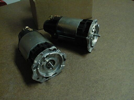
The units have arrived (Thanks Rich) complete with the original motors. These are secured to the gearbox with four M6 bolts. The motors are very similar
to those on my dynamics but with removable brushs. |
|
|
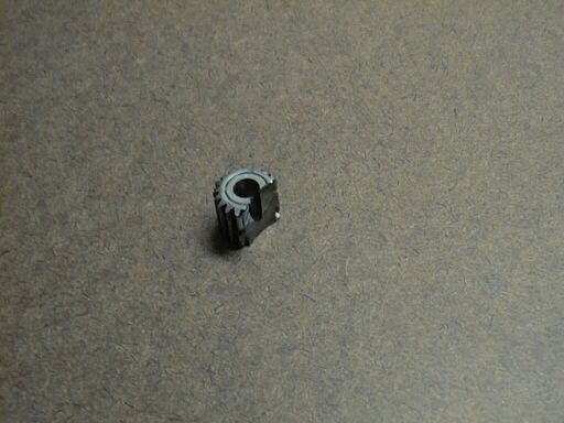
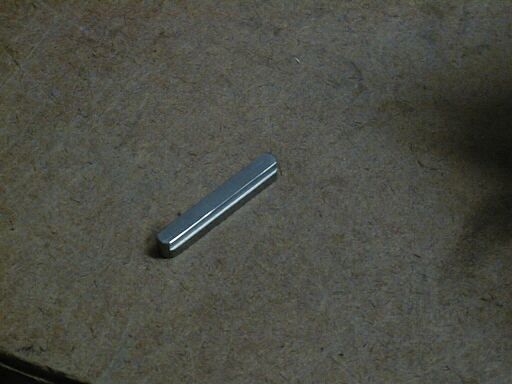
There was a moulded adapter between the gearbox input shaft and the shaft of the motor. Its probably there to reduce shock loads on the motor or box. A
similar solid adapter will be needed to mate the DeWalt motor to the box. |
|
|
|
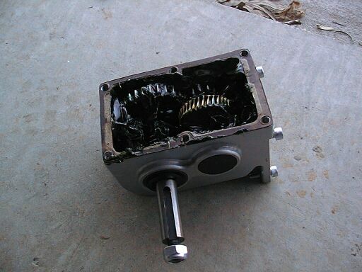
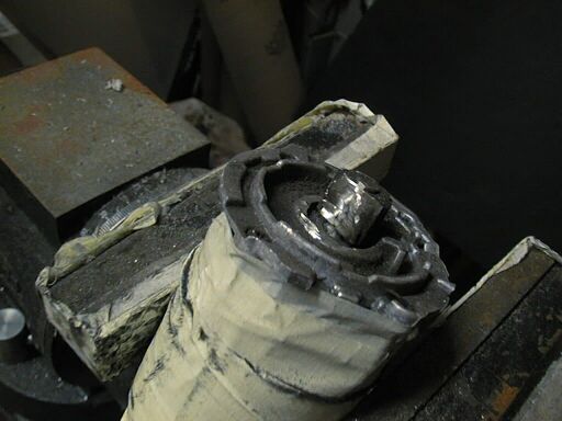
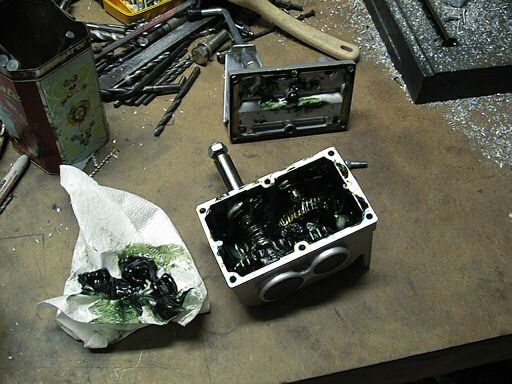
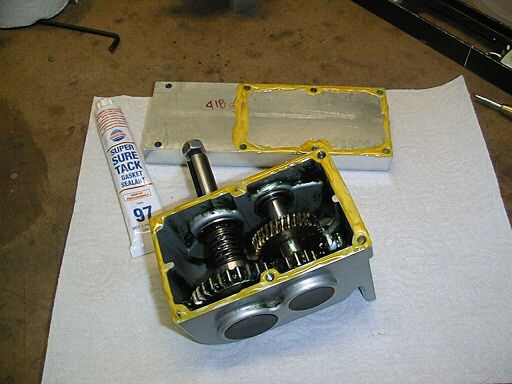
Opening the box reveals the spur and worm gears all bathed in a lovely green coloured grease. They have pretty big teeth (MOD 1.5?) and look capable of
coping with the planned 1HP and probably more. |
|
|
|
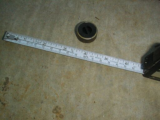
The drive "freewheel" release lever was removed by hacksaw after the pin retaining it refused to budge. The box alone weighs 4.75 lbs, not too bad
as it provides a mounted 17mm keyed driveshaft and an 32:1 reduction ratio. Next job is to model it in SolidWorks. |
|
|
|
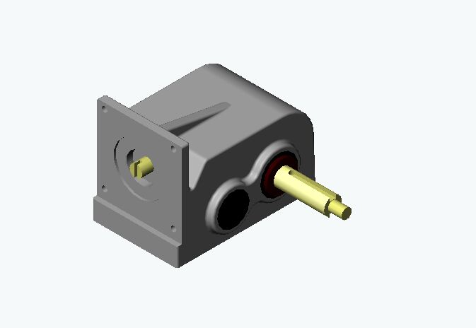
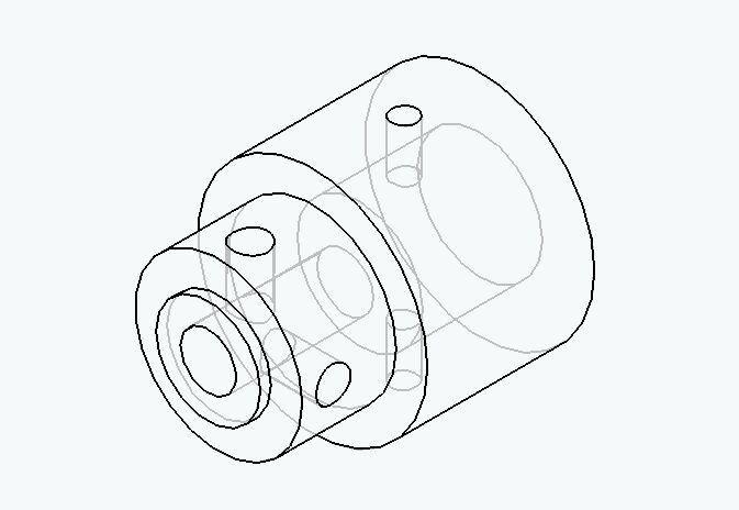
I have completed a solid model of one of the gearboxs and the other is identical except the shaft exits from the other side. An advantage of this
gearbox design is that both motors turn in the same direction so that motor timing doesn't matter. Handy because the DeWalts have forward timing. |
|
|
|
After much thought, I think the best way to join the shaft on the DeWalt to that of the gearbox will be via a machined adapter. A 3/32 hardened pin will
neatly fit the slot in the gearbox shaft and two M4 set screws will secure it to the DeWalt Shaft. I am going to send this model to a machine shop for a quote for a couple of prototypes. I
will wait until I have the actual motors to confirm the dimensions of the shaft etc before ordering the actual parts. |
|
|
|
|
|
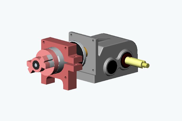
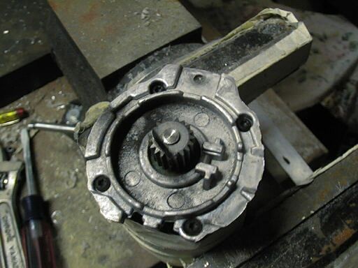
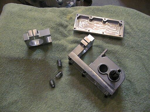
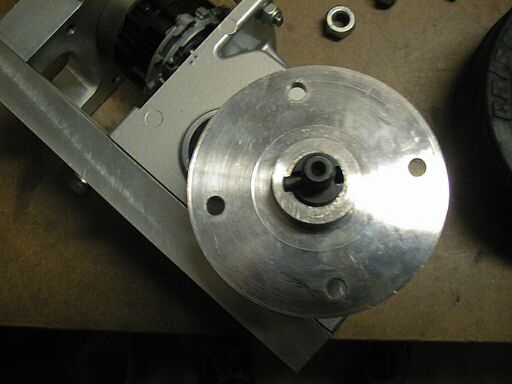
The second part of this project will be a method of mounting the motor to the gearbox. The gearbox has a nicely machined face with circular locating features and four M6
threaded mounting holes. Once I have the Dewalts I think there will be two options. First would be to machine an adapter that would match both the front bell housing of the motor and the face of the
gearbox and then add some sort of clamp back on the motor body to hold the whole thing together. The clamp is necessary as there are no mountings on the motor itself. The second option would be to
design the adapter to replace the front housing of the motor completely then the long screws that hold the motor together would also be attaching the motor to the adapter and perhaps no clamp would be
necessary. The latter option would be neater but I would have to have a good look at the motor itself to see this would be practical. |
|
|
|
|
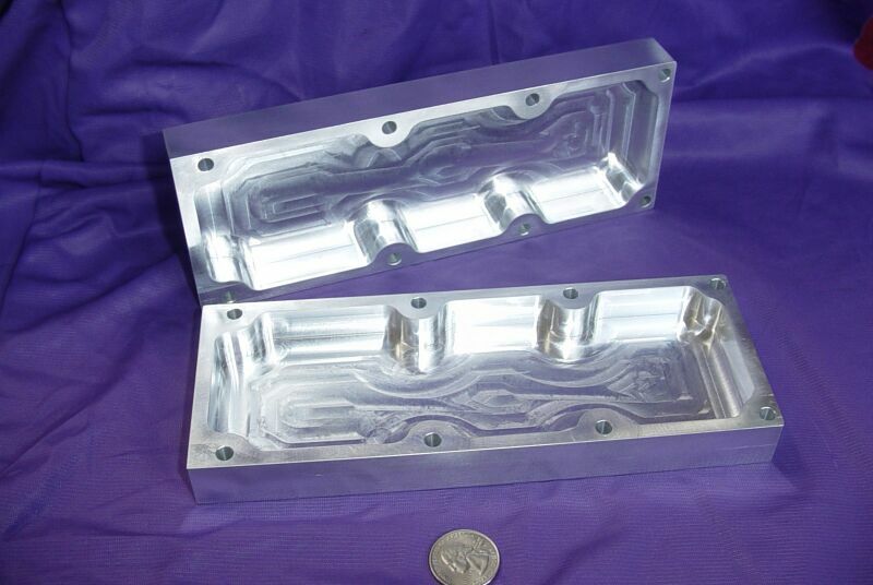
After much thought I came up with the motor mount shown in the attached picture. It will be machined from 1" thick 6061 Aluminium then attached to the
gearbox with long M6 screws and spacers and also each "leg" is tapped M6 so it can be attached to the baseplate alongside the Gearbox. This arrangement should result in a good
solid mounting whilst keeping the machined parts to a minimum and allowing easy motor replacement. |
|
|
|
|
The machine shop came back with a reasonable price for the adapters and I am sending the details of the
motor mount to them to find out how much they would cost and if they have any recommendations for changes that would simplify manufacture and hence reduce the price. |
|
|
|
|
|
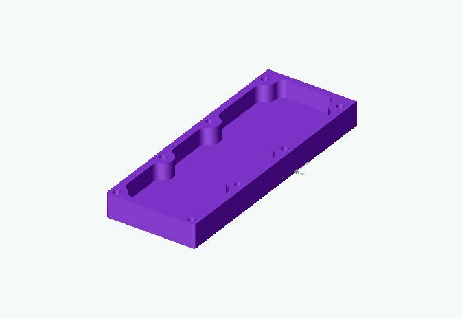
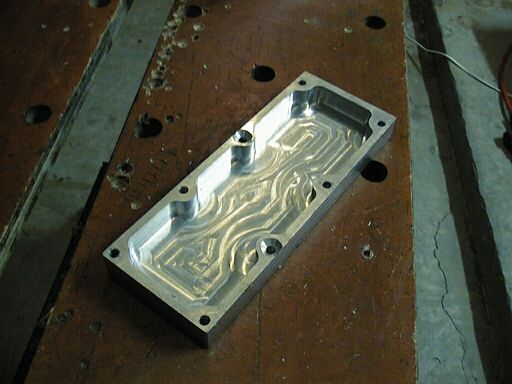
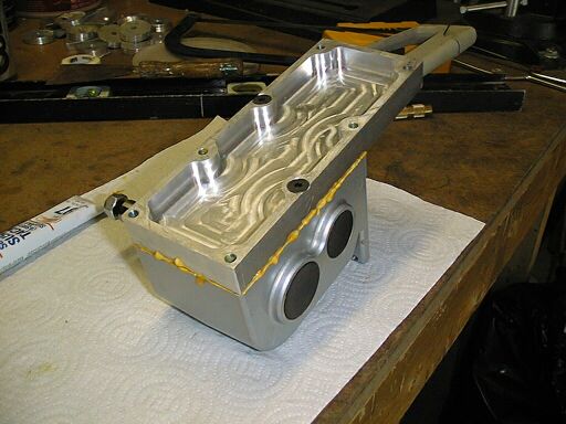
The last big part required is a spacer block to replace the cast top of the gearbox and to tie the motor mount and gearbox together. This part will be made
from UHMW to save weight. |
|
|
|
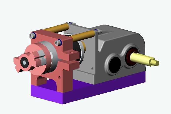
This is the completed assembly. A couple of long M6 bolts and spacers ensure that the motor is rigidly attached to the gearbox. All that still requires to
be done is to remove the gears from the two DeWalt 24v motors. I still need the shaft diameter dimension to complete the machined shaft adapter. |
|
|
|
|
Removing the gears from the Dewalts. |
|
|
|
|
|
|
|
|
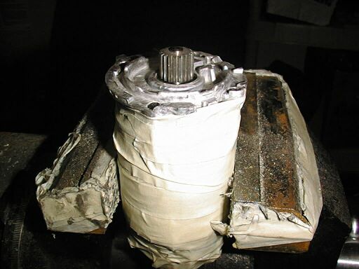
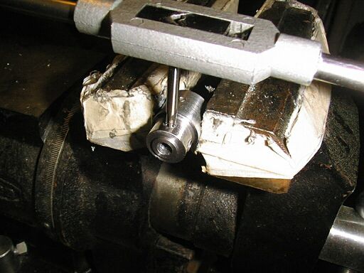
In order to fit the adapter to the DeWalt motor, the existing gear must be removed. First thing to do is to wrap the motor completely in tape to
protect it from metal filings. |
|
|
I bought a Bolink BL6014 puller. It proved not to be up to the job and snapped before the gear started to move. Levering with screwdrivers also failed to
move them. |
|
|
|
I decided to cut them off with my Black and Decker "Dremmel" tool. I started with a vertical cut down the side of the gear. It is very important to
wear safety goggles as the cut off disk will break apart suddenly and cause shrapnel in all directions. |
|
|
|
Continue cutting and grinding away at one one side of the gear until you can see a small crack or gap. Be careful not to grind too much of the shaft. A
little doesn't matter as a small flat will help the set screws grip the shaft better. |
|
|
|
When most of the gear has been ground away along one side it is easily levered off using a small screwdriver. I over did the grinding a bit on the first gear
as shown but the second was much better. |
|
|
|
I also needed to grind down the two small "bumps" on the casting next to the shaft so the adapters wouldn't hit them. The DeWalts are now ready.
|
|
|
|
|
The Shaft on the Dewalt is 2.2" in diameter. I have modified the little adapter to suit this shaft and made small changes as recommended by the machine shop plus a
couple of changes that will make the M4 setscrew holes easier to tap with the equipment I haveToday (March 13, 2003) I ordered all the various parts. Next job is to machine the baseplate to suit the
new gearboxs and alter the hubs to suit the larger keys used on the shafts. |
|
|
|
|
|
|
|
|
|
|
|
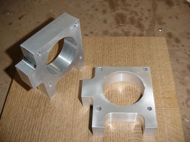
Gregg at the machine shop sent me this picture of the finished mounting blocks. They look really good and I'm looking forward to seeing the rest.
|
|
|
|
The DeWalt mounting blocks are almost finished, Gregg had a couple of change requests to simplify manufacture which I agreed to and the parts will all be
ready by the 2nd of April. |
|
|
|
All the parts have arrived. The drilled holes in the legs of the motor mounting block have been tapped M6 |
|
|
|
Here I'm tapping the four M4 set screw holes in the adapters. Tapping that small a thread in steel is tricky. I broke two taps and ruined one adapter before
I perfected the technique. . Luckily I had one spare one. |
|
|
|
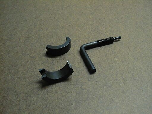
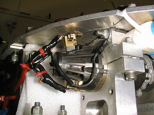
The adapters are secured to the motor shafts with four cone tipped set screws. I hope this will be enough to prevent failure. You can also see the 3/32
hardened steel pins used to engage the slot in the gearbox input shaft. These are a little loose and I needed to use tape to stop them coming out when the motor runs. |
|
|
|
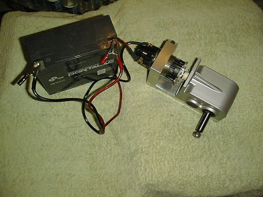
The gearbox runs for the first time! At 12v it seems as fast as it old ones were at 24v. Testing at 24v will follow later
. |
|
|
|
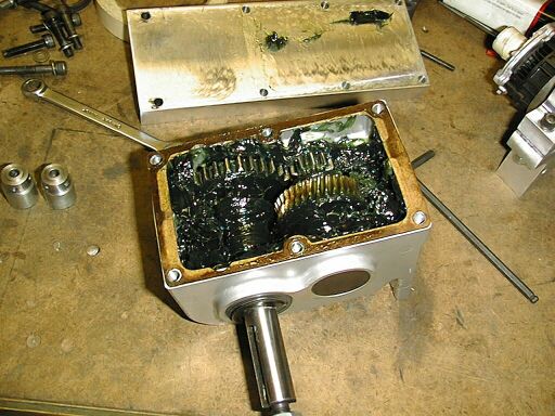
After a short run I removed the box to see how the gears are being lubricated. The photo shows that little grease is on the worm gear and that replacing
the grease with oil may be necessary. |
|
|
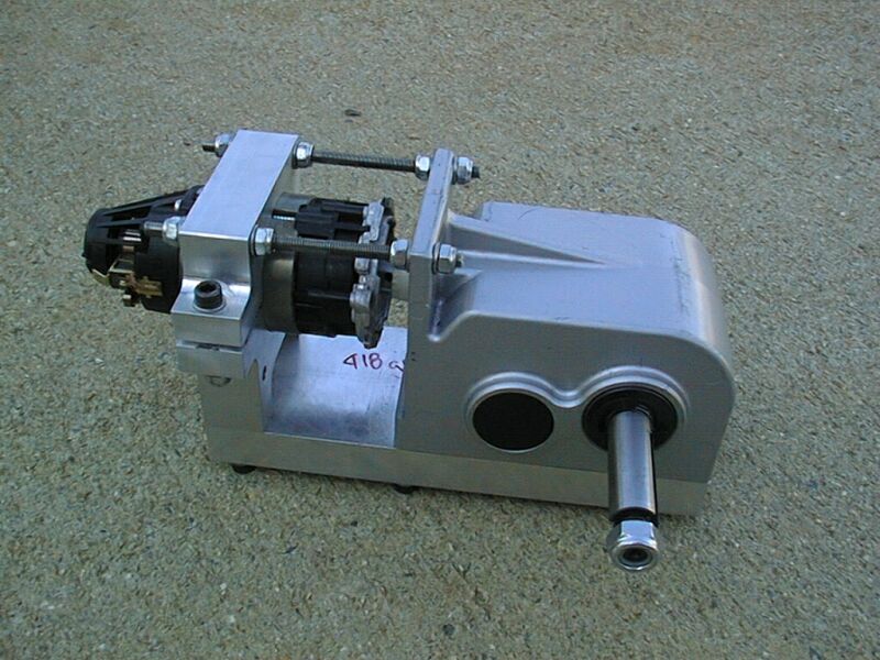
This BIG 800 x 600 picture shows the compete gearbox as originally designed. the tierods add stiffness and reduce noise and vibration. |
|
|
|
|
After some discussion in a post on the Delphi Battlebots forum
http://forums.delphiforums.com/BattleBot_Tech/start
I think I will remove the grease from the boxes and replace it with Transmission fluid or similar gear oil. This will require modifications to the mounting block so that it can remain solidly attached to the gearbox body even when not mounted in the Bot. This is to prevent messy leaks if I need to remove the assemblies from the Bot. I will also add a fluid filler hole in the top to allow easy level checking and top up. These modifications will allow the worm gear and worm to be constantly lubricated reducing power losses and wear.
|
|
|
|
|
|
|
|
|
|
|
|
|
Whilst the shaft on the new gearboxs is the same diameter as that on the old ones the keyways were different. The hubs were designed for 6mm keys and the
new shafts had 4.5mm keyways. You can buy stepped keyways but I couldn't find any metric ones so I had a friend machine the existing ones to fit. this is much easier and cheaper than adding
new keyways to the hubs. |
|
|
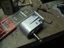
Here you can see the new keyway in place. |
|
|
|
I countersunk a couple of the mounting holes in the baseplates so that the gearbox could be attached to the plate separately and so keep the oil within
the unit when removed from the chassis. |
|
|
|
Next I had to remove as much of the grease from the box as possible using my fingers and lots of paper towels. |
|
|
|
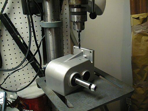
I stuffed the box with paper towels to catch any swarf the drilled a hole in the top of the box. |
|
|
|
The hole was tapped M6 and a short hex head screw will act as a oil filler cap. |
|
|
|
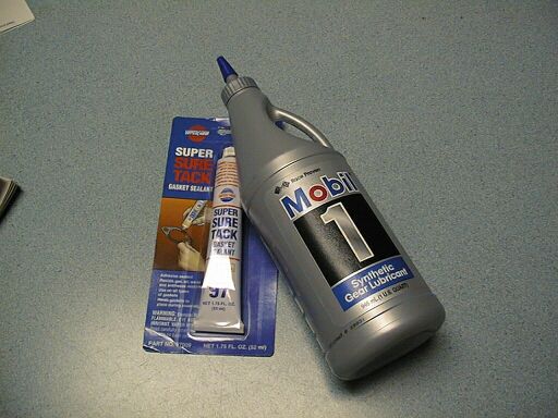
I have chosen a synthetic gear oil for the gearboxs. The bottle has the advantage of having a small spout which will make filling easier. The Sealant
should help reduce leaks. |
|
|
|
The sealant replaces the paper gasket that came with the gearboxs. It is applied to both faces and left for a few minutes until it is tacky. |
|
|
|
The baseplates were then screwed onto the gearboxs. The completed assemblies then mounted onto the baseplate |
|
|
|
At Robot Assault in our first fight with the new Gearbox a shock caused the brushes to become loose on the Dewalts. This shorted out one side of the Vantec.
This apparently is a known problem (but not to me!) and can be fixed by using a tiewrap or by using the Dustin Brush housing.
Update 8/2011 Sadly we never had the money to rebuild Xtreme impaX to be a competitive
design. The gearboxs had worked as planned and may see use again one day. However I hope the Gearbox article might give you some idea of waht can be achieved with a little ingenuity
|
|
|
|
|