|

|
|
|
Featherweight. |
|
|
|
|
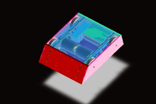
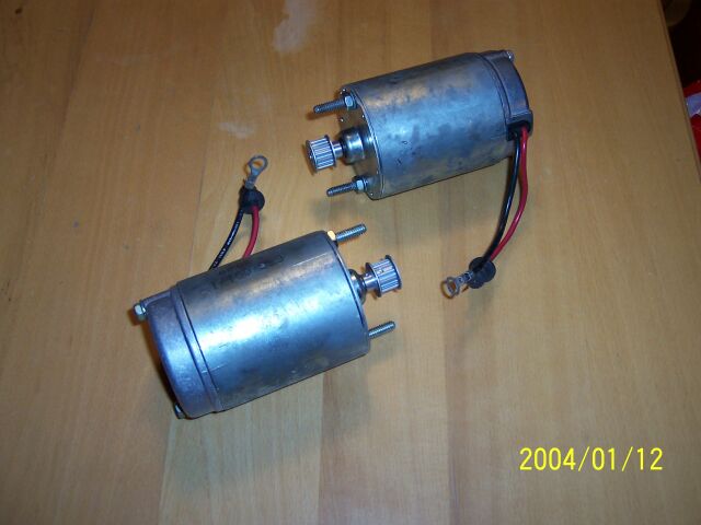
After NCRSF III, Andrews interest in Battlebots was brought to a peak and he wanted to design and build his own.He chose the design himself and its to be
a 6 x 6 wheel drive 30lb wedgebot. It will be powered by two A-Packs driving 4" wheels through 3.66:1 gearing using a 12v NiCad battlepack. He has even built a model of it as you can
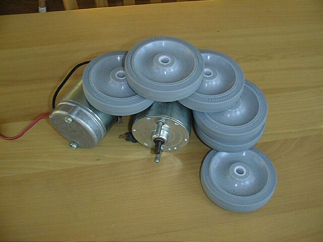
see in the attached photo. We have the motors and the wheels now and are currently working out how to connect them them all up cheaply and effectively. It is proving to be a fun
learning experiance for both of us. More soon as we hope to have it ready for the spring NCRSF IV. . |
|
|
|
|
|
Our Featherweight will be designed using Solidworks thanks to their generous offer of a free copy of the CAD software. |
|
|
|
|
|
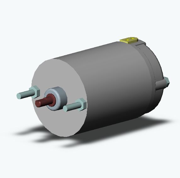
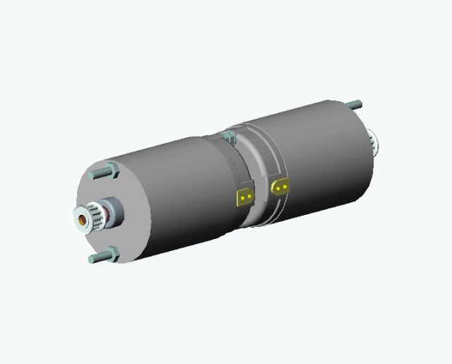
My first ever solidworks part. This is an fairly accurate 3D drawing of one of the A Pack motors. You can get the Solidworks file in the
Solid Models SectionI found Solidworks easy to learn and use. I have a slight advantage here as CAD is what I do for a living usually on Catia or PRO/E
|
|
|
|
|
|
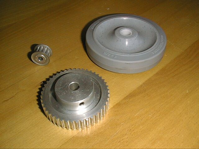
I ordered one 12 tooth and one 44 tooth 5mm pitch - 9mm wide HTD pulleys to trial mount to the wheels and motors.I got them from SDP at www.sdp-si.comThey have 3D files for a lot of their parts and
prices are not too bad. |
|
|
|
|
|
This is my first SolidWorks assembly. I created a sub assembly of the small pulley onto the motor and then a top assembly of the two motor/pulley assemblies
back to back. I had some problems getting everything aligned properly as the manual does not explain this well. |
|
|
|
|
|
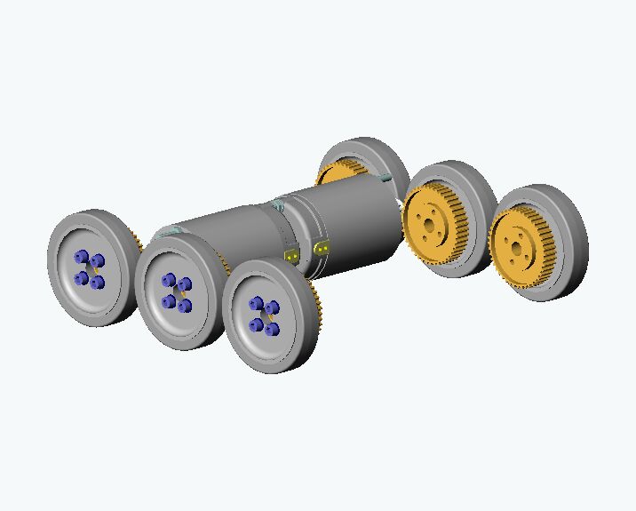
The Assembly grows. The wheels were mated to the big pulleys in a sub assembly with four M6 screws and then six of the sub assemblies were added to the tp
assembly. It quite easy to do this once you have worked out how! |
|
|
|
|
|
Added the Vantec 36E to the assembly. You can get the files for the Vantec without the added cover in the Solid Models
Section. |
|
|
|
|
|
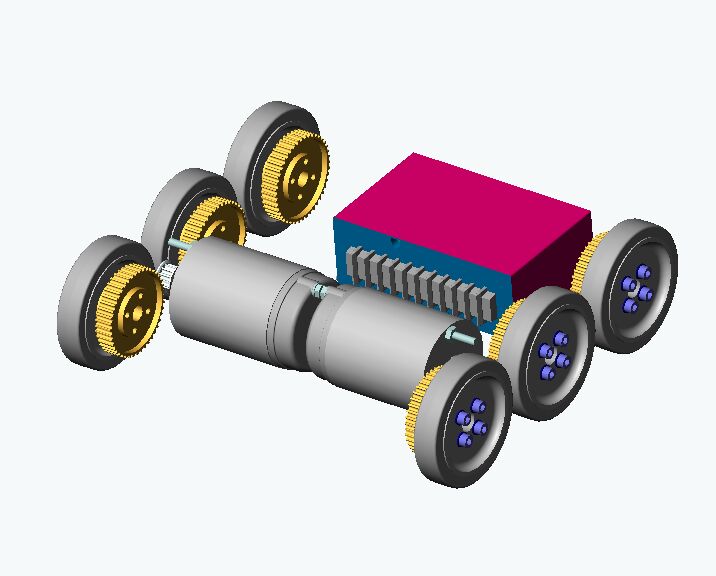
I have started designing the chassis around the mechanicals. There will be "tabs" and "slots" in each part so that the chassis will fit
together like a kit. As the chassis develops parts get moved around to suit. This is much cheaper and easier to do at this stage rather than when we have paid for actual parts. I also have
created a model of the required 12v NiCad Battlepack. |
|
|
|
|
|
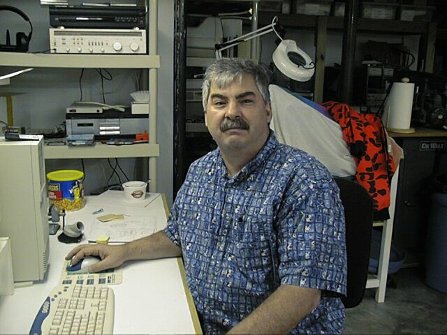
A friend, John Wettroth, has a small CNC Milling machine and he kindly offered to do the necessary work on the wheels and pulleys. John designs DRO's for
Sherline among other things. |
|
|
|
|
|
|
|
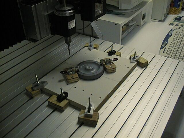
The Mill had been designed to cut out pieces of rigid insulation and was dismantled with some parts missing when John bought it. He rebuilt it with
Sherline Milling head etc. and is now ideal for milling plastics and nonferrous metals. He built a jig that allows quick and accurate alignment of the wheels and once setup it only takes a
couple of minutes to machine each wheel. |
|
|
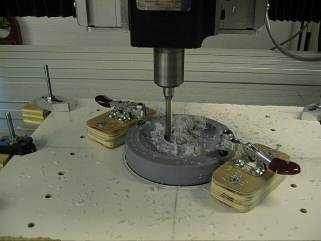
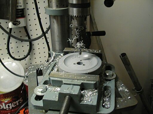
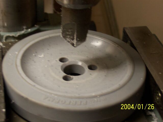
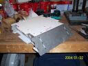
Machining the first side of the wheels. We still need to machine the other sides and then add the mounting hole pattern to match the pulleys. The machining
was required to give a flat surface for the pulleys and their mounting bolts to seat on. |
|
|
|
|
|
|
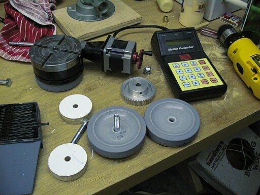
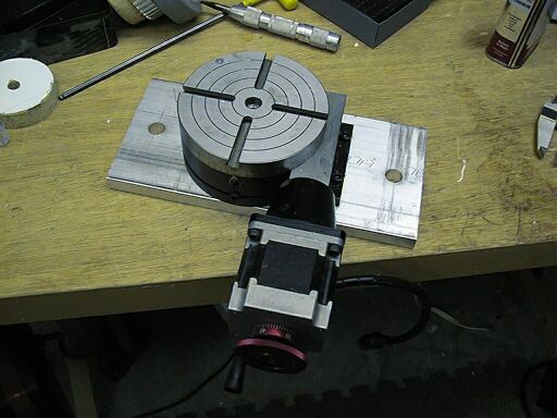
John has this really neat CNC rotary table. He was the the designer of the electronic and software for it and it was to prove very handy for drilling the
hole patterns in the wheels and gears. It uses a little battery powered "Calculator" to operate a stepper motor that drives the table. You can choose to move a certain angle or
fraction of a circle. |
|
|
|
|
|
We needed a small sleeve to match the bore of the wheels to that of the gears so that they could be mounted together on the table. John machined one up on
his Sherline. That's the DRO he designed for Sherline at the right hand side. Its a neat machine but a little small for bot building in the heavier weights. |
|
|
|
|
|
The rotary table was designed for Sherline mills but our job was to too tall to fit his and the table would not fit on his bigger mill. We solved the problem
by making a baseplate that fitted the mounting holes on the table and had holes that would fit the bigger mill. |
|
|
|
|
|
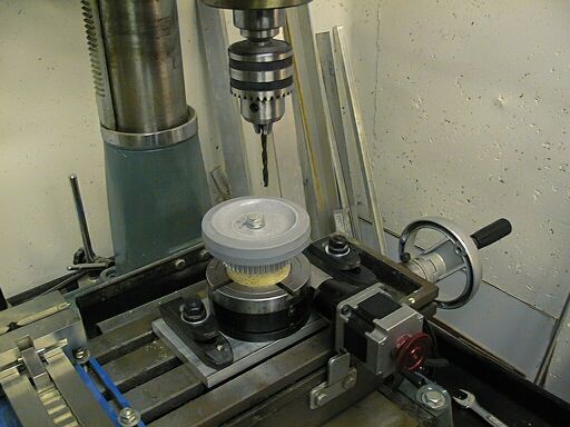
The table was mounted on the bigger mill. This is a Chinese built machine he got at a sale at Harbor Freight but has a circular post that is not particularly
good at keeping solidly locked. Still its pretty nice for $650 or so. |
|
|
|
|
|
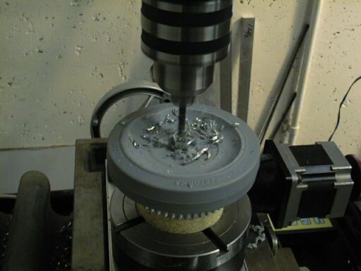
Drilling! We have the wheel and gears stacked up with a sacrificial wood block. The wood prevents damage to the table if we drill too far. It took
hours of set up to get everything ready but less that a hour to drill all six sets. We decided on three holes per wheel rather than the four in the original design because we could and
it'll save the weight of six M6 screws! |
|
|
|
|
|
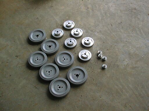
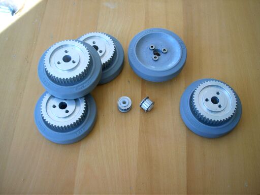
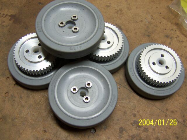
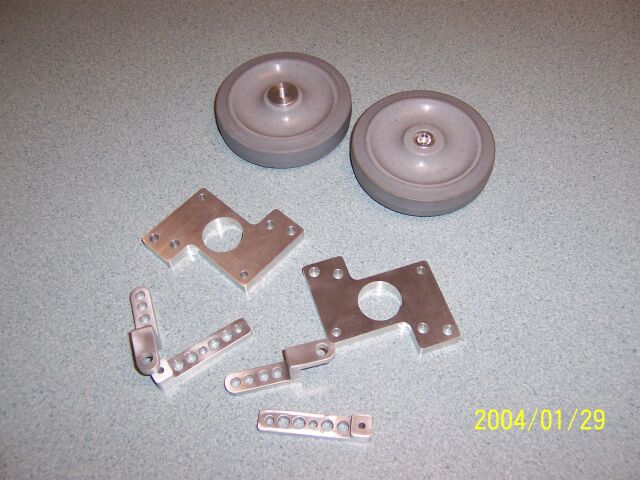
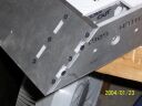
The wheels and gears after drilling. We still need to tap the hole M6 and open out the holes in the wheels to match. The small gears will be used on the
motors and for the tensioners (still to be designed!) |
|
|
|
|
November 1, 2003 |
|
|
|
After a break over the summer when we had to concentrate on the other bots to get them ready for the 2003 Robot Assault competition, I have restarted design work on
the Featherweight. One big change decided on after a lot of thought was the move from six wheel drive to four wheel drive. This was done for two reasons, weight was getting very tight (calculated
using the Solidworks volume/weight function) and secondly because it was proving hard to design in the tensioner pulleys so that all the pulleys would have sufficient engagement with the belt.
|
|
|
|
|
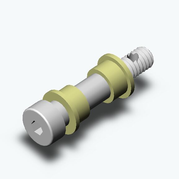
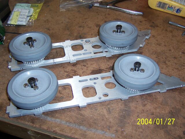
First thing to do was build up the axle assemblies. The wheel will rotate on fixed axles. We will use 3/8" shoulder screws with the shoulder acting as
the bearing surface. Two nylon Flanged bushes will be the bearings as shown. Models for the shoulder screws can be found on
www.mcmaster.comwhich saved a bit of design time |
|
|
|
|
|
The pulley fits between the flanged bushes with the hub facing out. Any axial play of the pulley/bushes on the axle will be controlled by adding nylon or
teflon spacers. |
|
|
|
|
|
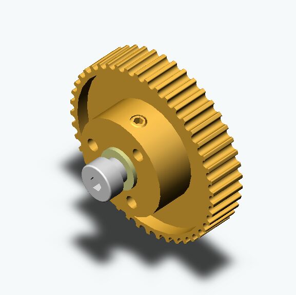
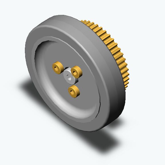
The Wheel and hub were redesigned with the three mounting holes as per the actual parts and assembled together using three M6 low profile hex head screws.
Models for the screws can again be found on McMaster. |
|
|
|
|
|
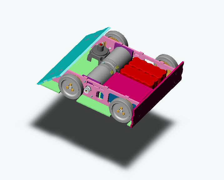
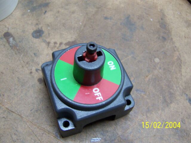
The top assembly was modified to show the change to 4WD and I also added most of the remaining large components. The power switch is from www.westmarine.com
and I'm showing two 3600 NiCad Battlepacks but I think a couple of 2400s would be enough. |
|
|
|
|
December 10, 2003 |
|
|
|
|
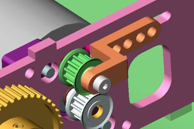
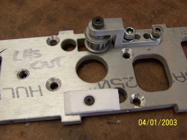
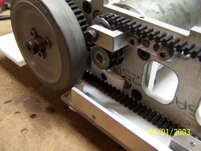
Going to 4WD simplified the tensioner arrangement. The tensioners each consist of two machined Aluminium parts and a 1/4" Shoulder Screw to mount a 12
tooth idler pulley as shown. The blocks are held together by a couple of M6 Screws (not shown). The slots in the chassis give a about 12mm travel. |
|
|
|
|
|
|
|
|
|
|
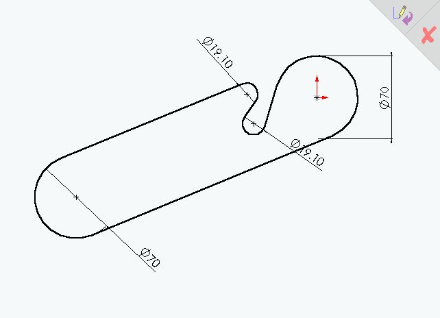
In Solidworks assembly mode I was able to draw up a sketch of the belt centreline using the pitch diameters for each of the pulleys. the Measure function
was then used to give a belt length of 748mm at maximum tensioner position. I then ordered the next size down, 740mm, from
Sdp/Si. |
|
|
Another function in Solidworks then let me add the belt thickness on either side of the centreline giving me the limits of the belt itself so that I
could check for interferences. Notice the A-Pack mounting bolt hits the tensioner pulley at maximum tension. I resolved this by modifying the spacer plates so that the motor is mounted to
it and then the hole assembly is mounted with flat head screws thus removing problems in this area. |
|
|
|
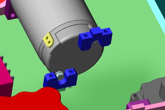
In order to support the backs of the heavy motors I have designed a couple of blocks that will be fitted to the top and bottom covers that will act on the
bolt heads on the end plate of the motors. I may instead use threaded rod to hold both motors together as one big assembly but even in this case the blocks would still work on the spacers
that would be required between the two motors. An added complexity is that the cables from the On/Off switch etc. have to be able to pass through this area as well. |
|
|
|
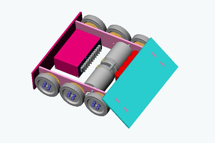
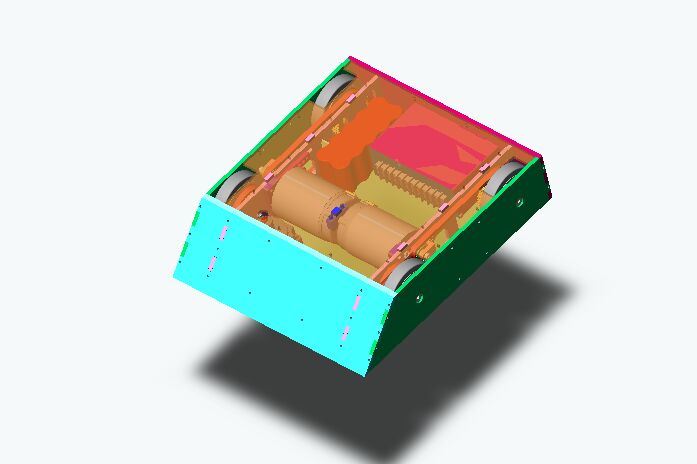
Almost finished the Design! I have added multiple holes for the M4 flat head screws that will be used to hold the whole thing together and I also found
the "transparency" setting on Solidworks so now the Top and Bottom Lexan panels are see-through. |
|
|
|
|
|
I just put in an order to McMaster for all the shoulder screws, nylon bearings etc. we will need, The Belts are on their way already and I have sent the Solidworks files
of the tensioners and motor spacers to cncbotparts (sadly now out of business) for
them to quote. The Vantec 36E just came back from Vantec where it was getting fixed after damaging it at RA in Xtreme impaX.Next job is to create dxf files of all the chassis panels to get the
quotes for the necessary water cutting. Deadline for getting this bot built is Late February for Motorama, looks like we should make it. |
|
|
|
December 29, 2003 |
|
|
|
In between completing the design for the 30lber and working on a new 12lber design to replace Cheep Shot we worked on the wheels and sprockets. |
|
|
|
|
|
|
|
|
|
|
|
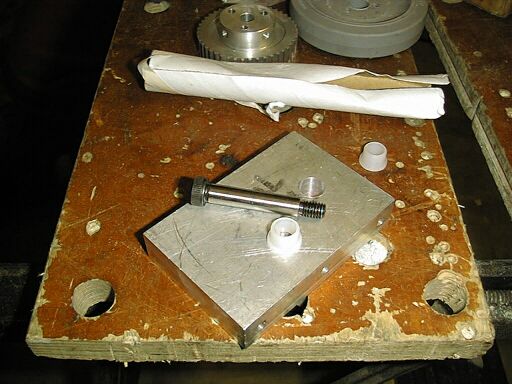
This is one of the 3/8" Shoulder screws that will act as axles for the main drive wheels. The pulleys needed to be drilled out to 1/2" so that the
matching nylon bushes could be fitted. This was a trial hole in a scrap chunk of Aluminium. |
|
|
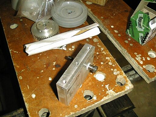
Here one of the shoulder screws can be seen fitted into the hole with its bushes. The bush is a little loose in the hole, probably due to the 1/2 drill I
used being a bit worn. I tried a 12.5mm Bit I had but that hole was too small and although the bush could be pressed in the Shoulder screw was a very tight fit. |
|
|
|
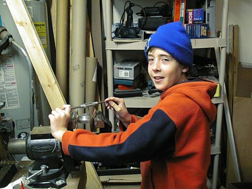
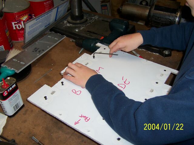
After drilling out the centres of each Sprocket we then tapped M6 the three wheel mounting holes in each one. Since we we had five sets to do I taught my
son how to do it and helped with a couple. |
|
|
Then we had to drill out the matching holes in the Wheels to give a clearance fit for the M6 screws. Normally a 1/4" drill (6.35mm) is good for this but
we found that due to inaccuracies in the hole patterns we need to use a 9/32" so that all the wheels could be properly centred on the gears. |
|
|
|
The same process was carried out for the two small sprockets that will be used as tensioners and those and the assembled wheel and sprockets can be seen
here. |
|
|
|
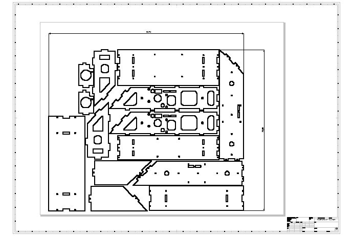
I created a trial drawing and DXF file of the top and bottom panels for sending to the water cut folks to check that it works for them. The local place said
it will save money if I can lay out all the parts (for a given mat'l) in one file so that they can cut it all in one go. I plan to add the parts for the new 12lber to be cut at the same
time. |
|
|
|
|
|
January 11, 2004 |
|
|
|
|
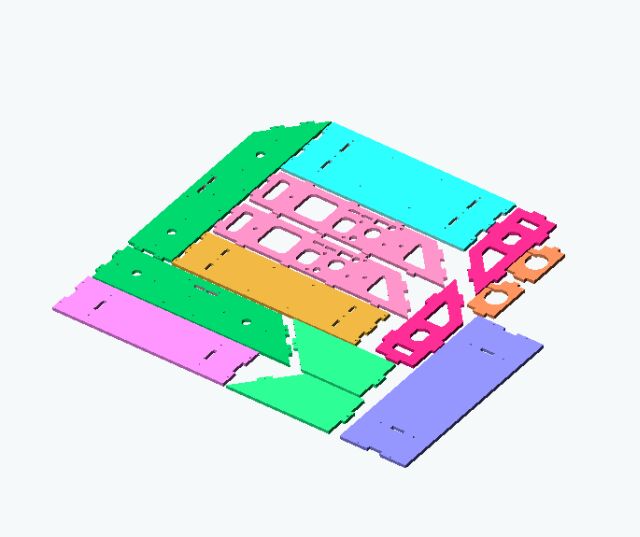
I laid all the .25" Aluminium parts out in one assembly and positioned about 3mm apart (to allow room for the waterjet itself) and then created a
drawing from that assembly. I did the same for the Lexan top and bottom panels as well. I added the parts for the new 12lber, "Cheepshot 2.0" to get them cut at the same time,
hopefully saving money and time. |
|
|
|
|
|
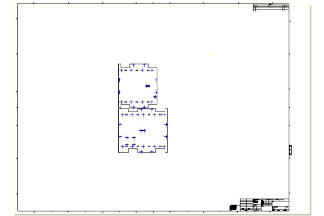
The drawing was laid out 1:1 scale on a A0 sheet and a couple of dimensions were added so that the watercut folks don't make a mistake of scale. It is then
saved as a dxf file which has been sent to a couple of places for quotes. |
|
|
|
|
January 12, 2004 |
|
|
|
|
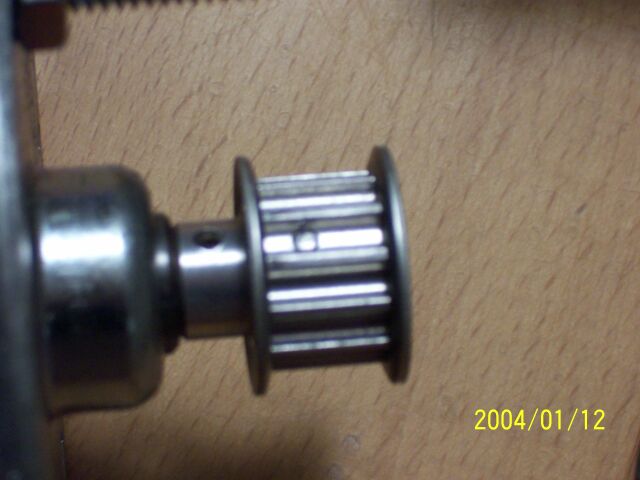
A workmate drilled out two small pulleys to fit the non-standard shafts on the A-Packs and then fitted pins to ensure they stay on and don't slip. |
|
|
|
|
|
The pins were positioned in the toothed part of the pulley as there was a lot mone metal here than in the drilled out hubs. The pins were carefully sized so
that they will not affect the belt. |
|
|
|
|
Got the first quote back for all the Watercutting of the Aluminium parts, $235 all in which doesn't seem too bad considering the metal alone would be well over $100 from
McMaster. Should get the second quote tomorrow. |
|
|
|
January 19, 2004 |
|
|
|
|
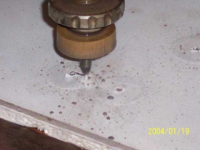
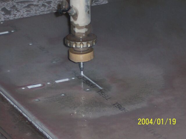
A big day in the building of Xhilerating impaX!We got the watercutting done on the parts for both the 30 and 12lbers at one time. |
|
|
|
|
|
And here the 0.25" 6061-T6 parts are being cut out. |
|
|
|
|
|
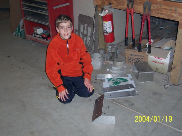
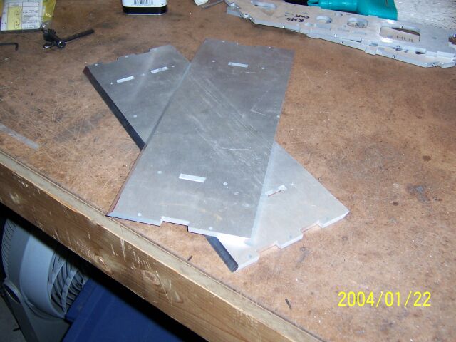
Andrew trial fitting some of the parts together. That's the wedge and side of the 12lber. Cutting was done by ADR hydrocut here in Morrisville N.C.
Contact me if you want more details. |
|
|
|
|
|
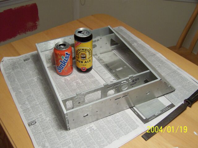
After a little filing all the main parts could be fitted together tightly. The beverages of choice for myself and my son give a sense of scale. |
|
|
|
|
|
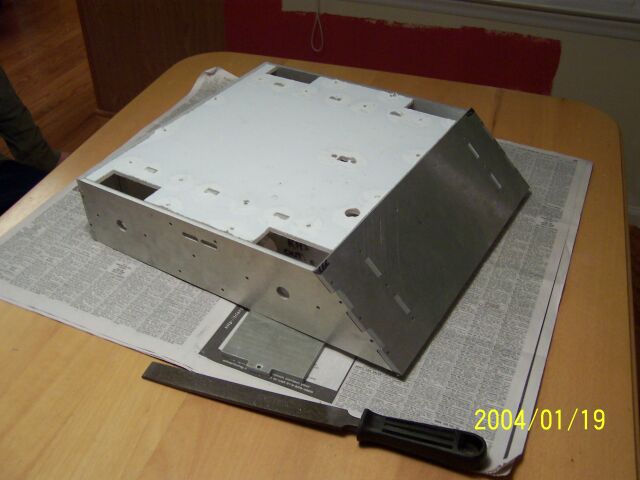
The top and bottom Lexan (actually the brand used was Hyzod) panels fitted without any filing and the bot is looking really good now. Still a lot of work to
go but it great now that real progress is being made! One month to go to Motorama. |
|
|
|
|
January 20, 2004 |
|
|
|
|
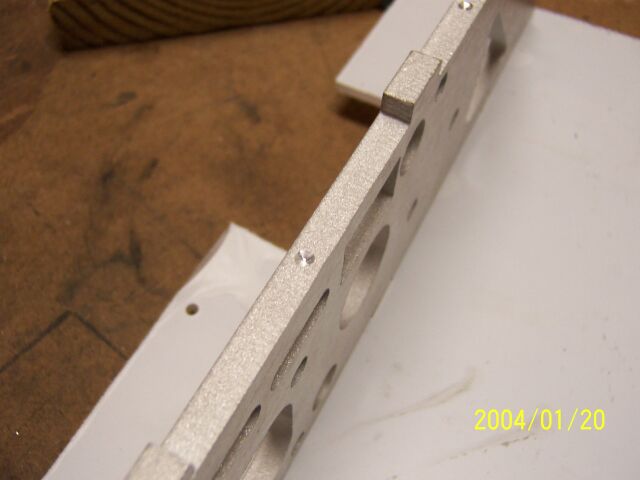
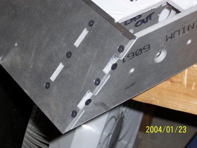
We spot drilled through all the screw holes so we knew where to drill and tap so that the chassis could be screwed solidly together with multiple M4 flathead
screws. |
|
|
|
|
|
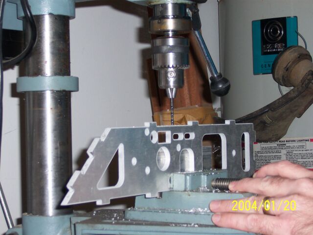
And then drilled each hole deep enough to allow us to tap it for the screws. Some of the holes could have been placed better so that they avoided other
features but nothing that will give us too many problems. |
|
|
|
|
|
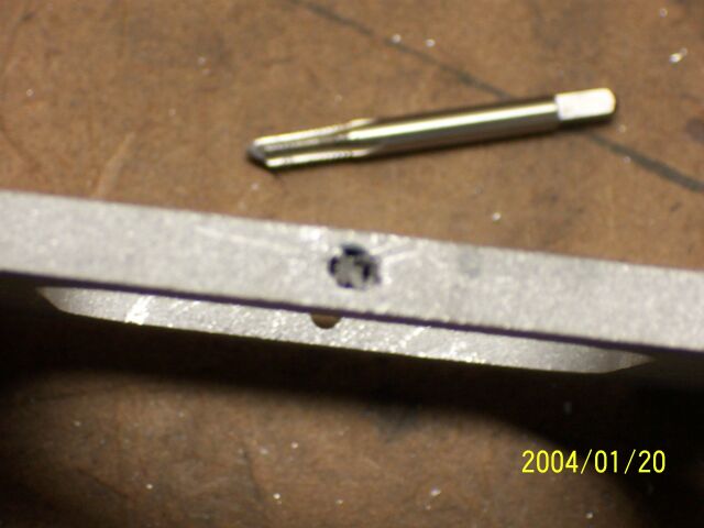
We then tapped each hole with first a Taper and then a Bottoming tap on any of the blind holes. After each was tapped we tried a screw in it to make sure it
was deep enough and the threads were good. |
|
|
|
|
|
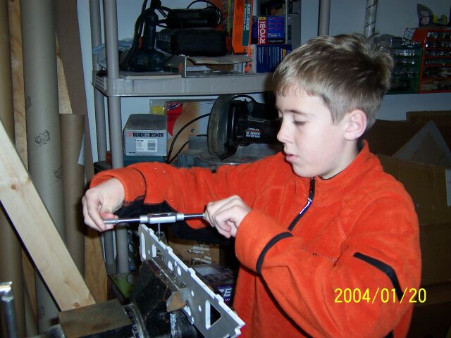
Tapping went very fast at first with the new Taps but later it started to get a bit slower and we should have slowed down and used oil when tapping but found
this the hard way when andrew boke the tap off in the hole. We will have to drill a new hole alongside as we could not get the remains of the tap out. We have complete 26 taps so far so
about half done! |
|
|
|
|
January 24, 2004 |
|
|
|
|
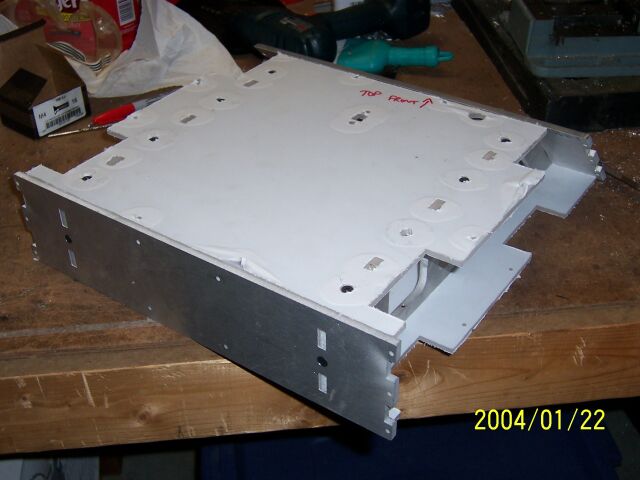
The pilot holes in the the bottom panel were drilled out and countersunk and then the inner side panels were attached with M4 flathead grade 8 screws.
|
|
|
|
|
|
|
|
|
|
The front wedges for both the 30 and 12lbers have had the edges beveled by a colleague. |
|
|
|
|
|
|
|
|
|
|
The drilling, tapping and countersinking continues panel by panel until just the left hand side armour still needs to be completed. The Chassis will then be stripped
down again to work on installing the wheels and drivetrain. The Tensioners and motor mounting blocks should arrive early next week.So far the assembly has gone pretty smoothly and shows the value of
spending a lot of time at the CAD stage to get it right. |
|
|
|
January 26, 2004 |
|
|
|
|
|
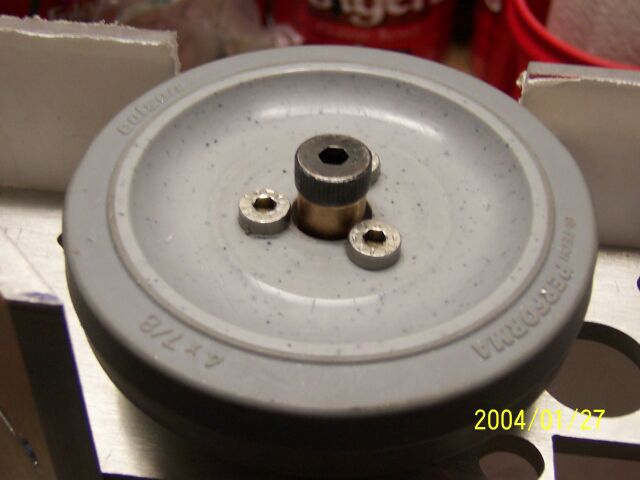
One last job needed done to the wheel assemblies. The backs of the wheels are being countersunk to add some clearance for the flanges on the Bushes that
mount in the Sprocket hubs. |
|
|
The bushes can be seen fitted into either side of the hubs. |
|
|
|
|
|
The tensioners etc were sent last friday so hopefully they will come soon. In the meantime I'll tap the axle mounting holes in the inner side walls and let us
trial mount the wheels into the chassis. |
|
|
|
January 27, 2004 |
|
|
|
|
|
|
|
|
|
|
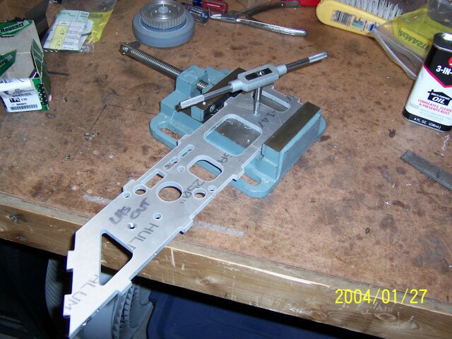
Tapping the axle mounting holes 5/16-18 to match the threads on the shoulder screws. |
|
|
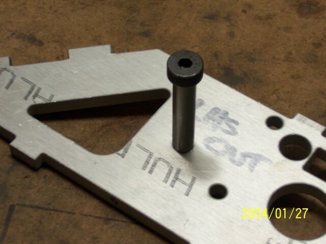
The axles simply screw into the side wall as shown and provide a high quality running surface for the nylon bushes in the hubs. |
|
|
|
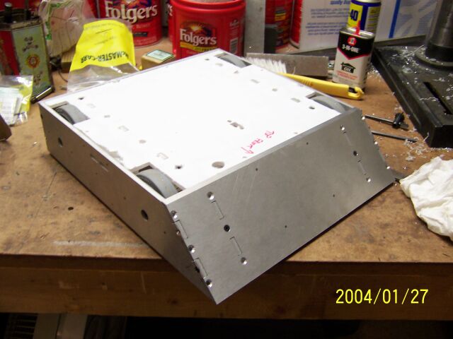
All four axles fitted. There is still a lot of end play of the hubs on the axles so I needed to make some spacers to fill the gap. |
|
|
|
I cut some bronze spacers with the correct internal diameter to length. |
|
|
|
And fitted them between the head of the shoulder screw and the hub. A couple of other nylon washers (not shown) make up the assembly so that little end
play remains and the hub spins freely. |
|
|
|
The bot runs on its own wheels for the first time. The ground clearance is about 3/16". |
|
|
|
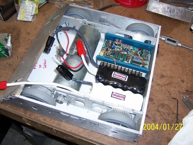
A quick trial layout of the internal parts shows no obvious problems. |
|
|
|
|
|
January 31, 2004 |
|
|
|
|
|
|
|
|
|
|
|
|
|
The parts from cncbotparts
have arrived. They machined the tensioners and the spacer blocks for the motors. The Wheels are for CheepShot 2.0. |
|
|
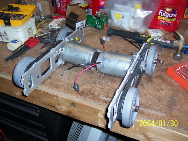
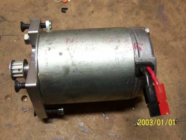
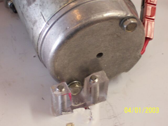
First job was to mount the motors to the spacers. This involved shortening the mounting bolts on the motors and tapping two M6 holes in the spacer. |
|
|
|
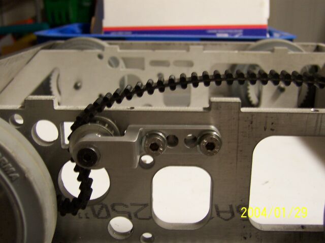
Next the tensioners were assembled. The rear block needed two M6 and one 10-24 threads tapped in it. The M6 is for the mounting screws and the 10-24 is for
the shoulder screw that acts as an axle for the tensioner pulley. |
|
|
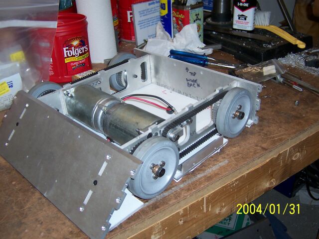
|
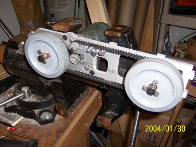
This is the first side of the drivetrain fully assembled. Fitting the belt is tricky as there really is not enough travel in the tensioner to allow the belt
to loosen enough to get it over all the gears easily. |
|
|
|
We then assembled the other side and tested it as well. |
|
|
|
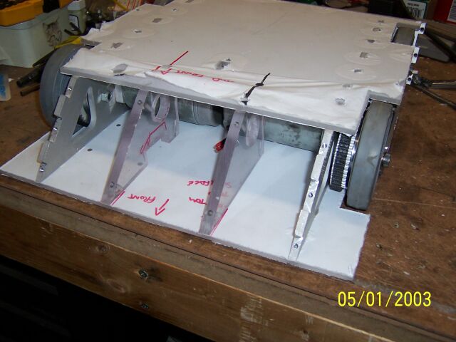
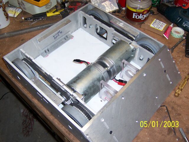
And then both assembles were built back into the chassis. Everything fits as it should. |
|
|
|
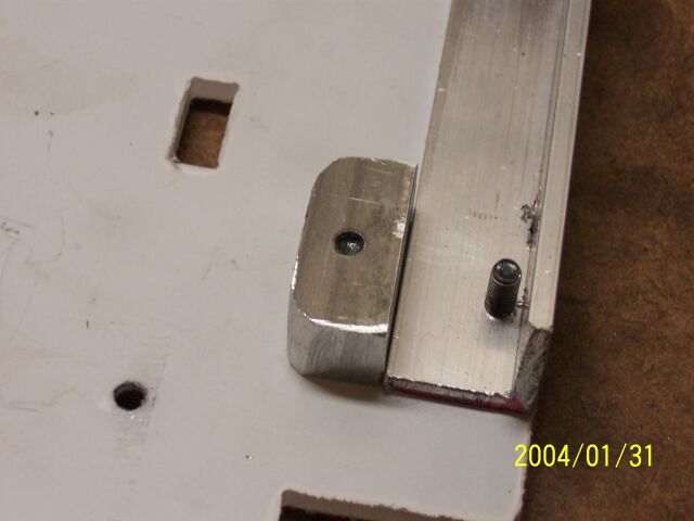
The base requires a few extra brackets to fully mount it to the rest of the chassis. We used short sections of Aluminium angle for the sides and rear and
these Lexan Blocks at the front. The are edge tapped and screwed to both the front and bottom panels. |
|
|
|
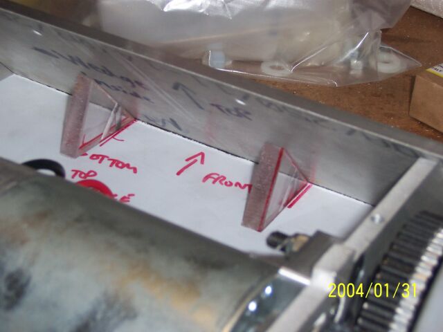
The belts had a slight tendency to wander a bit on the pulleys and we found even slight pressure on the side of the belt could keep it straight on the
pulley. Two small shaped aluminium blocks were mounted on the base plate to restrict outward travel of the belt. |
|
|
|
|
|
Febuary 13, 2004 |
|
|
|
|
|
|
|
|
|
|
|
|
Again to stop the belt tracking too far inwards small shaped blocks of Delrin (a slippery nylon like plastic) were added beneath where the motor pulley
comes through the inner wall. |
|
|
Both the aluminium and delrin guides can be seen here. |
|
|
|
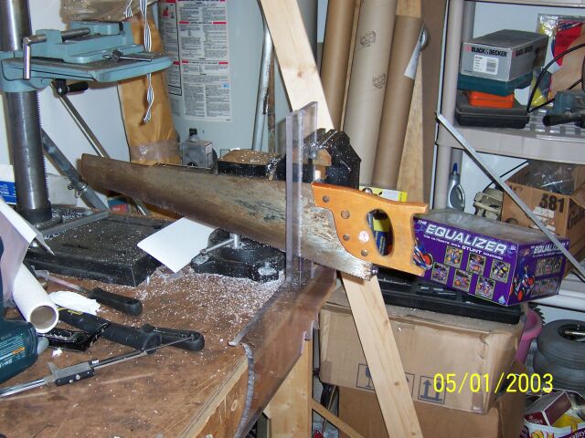
I decided to increase the size of the the two Lexan blocks at the front of the chassis. My jigsaw is worn out so I had to use cruder methods of cutting out
the shapes, Actually worked very well! |
|
|
|
The two new bigger blocks can be seen here. They also stop forward movement of the motors during big hits. |
|
|
|
I replace the connectors that come as standard on the A-Packs with a couple of 45A Powerpoles. These are a lot neater than the big 75A ones but much harder
to crimp properly even with the "right" tool. |
|
|
|
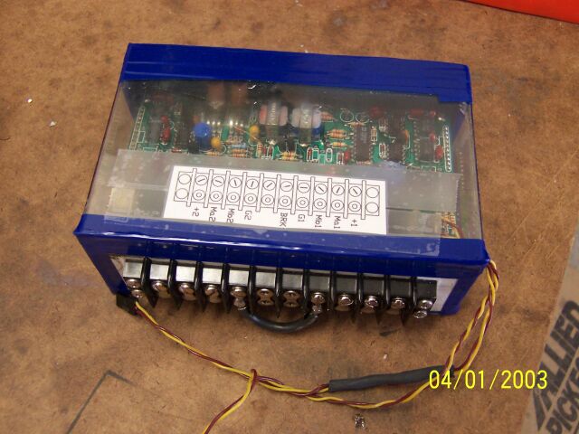
The repaired Vantec was protected by replacing the lexan cover I had on it in Xtreme impaX plus some tape to seal up any gaps left over to keep out
anything that may short it out. |
|
|
|
A small Lexan block was shaped to fit around the heads of the Moters bottom bolts. This helps keep the motors moving front and back. |
|
|
|
I have added the remaining sections of aluminium angle to secure the top cover to the sides and rear. |
|
|
|
The wiring was pretty straightforward and soon the bot was about ready for its first test run. |
|
|
|
|
|
First test in the garage had motors reversed etc. but by swapping motor leads etc. on the Vantec I soon had it running and steering correctly. Another problem showed up
when the Main power switch didn't work. I stripped it down (very easy) and found that it had been assembled incorrectly (possibly by Mark when he modified the Knob. I fixed that and also filed the stub
to a hex so we could use a hex socket to work it (but it is rapidly rounding off so we need to rethink this).Here is a
6 MB movie
of its first street test run. The bot is a fast and as maneuverable as we could want and seem to have plenty power. Motors only got warm after 8 minutes of running about and battery life seem good.
|
|
|
|
Febuary 19, 2004 |
|
|
|
|
|
|
|
|
|
|
|
|
|
|
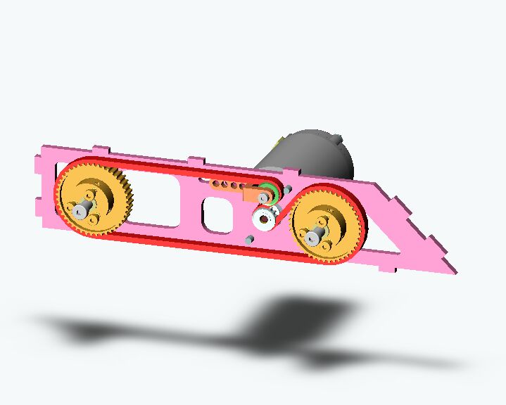
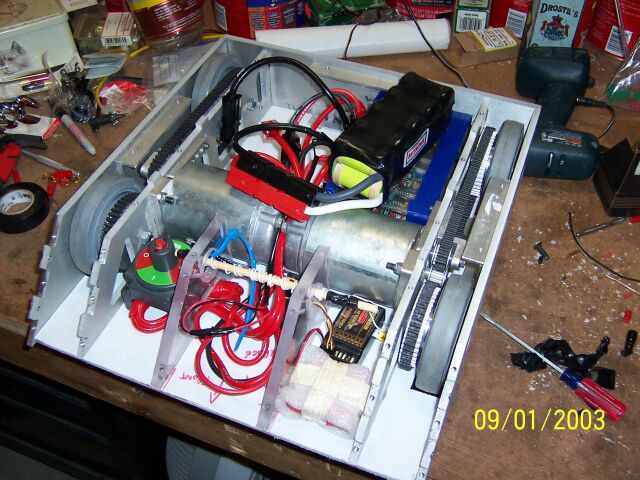
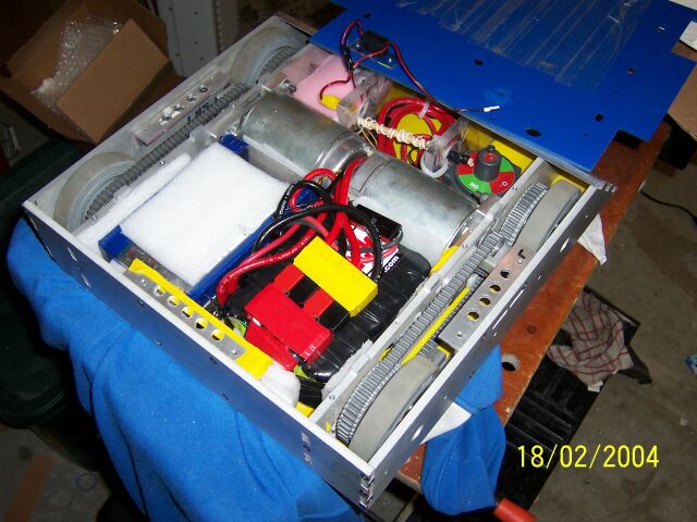
Another view of the internal layout |
|
|
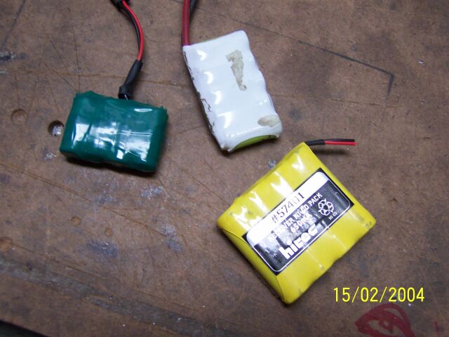
We knew we were very close to the weight limit so decided to save a few ounces by making a smaller RX pack out of one of my antweight Battlepacks. |
|
|
|
Filing the top of the West Marine power switch to a Hex was not a success as it quickly rounded off so I drilled and taped a hole in the top and epoxyed a
M4 hex head screw into it. Worked great! |
|
|
|
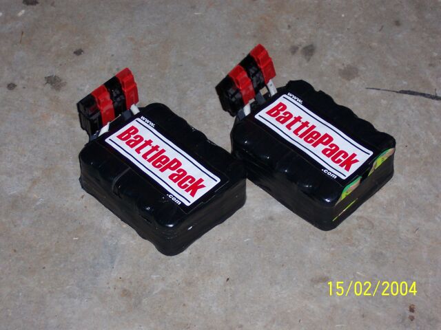
WE taped the 12v 3600Ah Battlepacks into pairs to make them easier to handle and charge. |
|
|
|
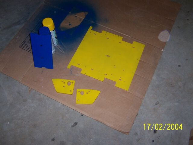
We painted the lexan parts in team colours using Krylon Fusion Paints on the inside surfaces. |
|
|
|
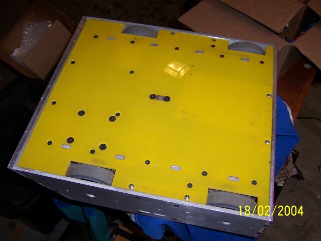
Here is a clear view of the completed underside of the bot. |
|
|
|
A final shot of the interior before screwing on the top the night before setting off for Motorama. |
|
|
|
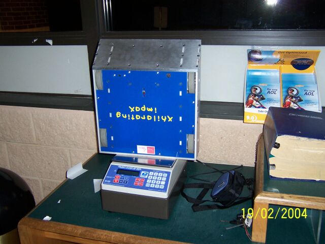
A trip up to our local Post office (open 24hrs for weigh-ins!) showed the weight to be 29lbs 15.4 ozs, a little too close for comfort! |
|
|
|
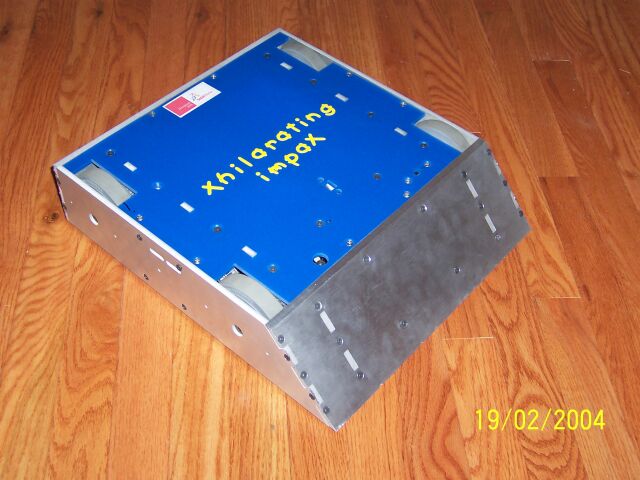
Xhilarating impaX all ready for its first competition.Motorama, here we come. |
|
|
|
|