|

|
|
|
CheepShot 3.0 |
|
|
|
CheepShot 2.0s relative success despite its obvious shortcomings has encouraged me to design a new 4WD 12lber using what worked i.e. the Harbor Freight Drill gearboxes
and the Mtroniks ESCs and replace what didn't i.e. the Short 2WD layout. I also wanted to include what had been pretty successful in our 30lber Xhilarating impaX, good solid armour and the space and
weight to upgrade armour and or power as required. |
|
|
|
|
I had tried originally to design a 4WD drive setup for CheepShot 2.0 but I could not get a design that allow the use of the Vantec to allow
higher voltages and still have reasonable armour. I know I need to get new smaller ESCs like Victor 833s but too many competing demands on my income prevented that. |
|
|
|
|
One other problem with going with four motors is that they force the bot to be wide and therefore heavy if any reasonable armour is used. Test Bot at RCRA showed this.
He was successful all day using to his wide wedge and good power to beat all comers until he met "Little Yellow Bus" in the final. Yellow Bus's Blade spinner took him apart for a decisive win.
|
|
|
|
I also wanted to make use of water cutting again but did not want to do all the end tapping that had required on our first two water cut bots so I worked hard on
designing a chassis that would use an alternative method of holding it together. The last problem to overcome was to come up with an easy, cheap way to attach Belt sprockets and wheels at the
same time to a Harbor Freight Drill motor/gearbox. |
|
|
|
|
|
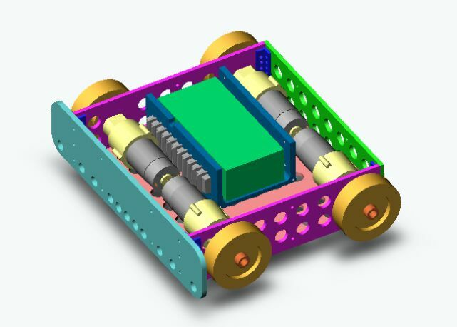
Design is progressing and the method of attaching the pulleys to the Wheels has been worked out. the pulleys require a little machining but nothing too
complicated. The wheels that are driven by the belts will have nylon bushes on fixed Shoulder screws as axles much as was done on our 30lber Xhilarating impaX.The bot is designed to be able to
handle ESC's as big as a pair of Victors as well as the smaller hobby types like the Mtroniks. |
|
|
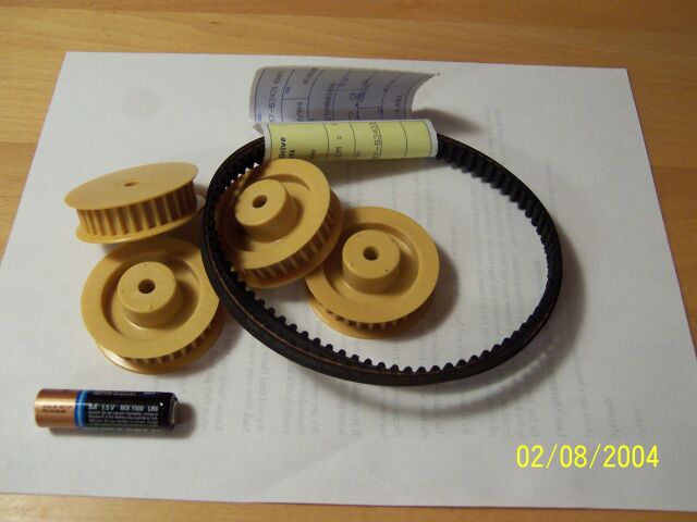
The first parts to be ordered were the sprockets and belts. The sprockets are from SDP/SI and do not exactly match the 3D CAD models from their website so
slight changes to the design were made to deal with that. The sprockets are currently being machined as required. |
|
|
|
|
|
I had hoped that this bot would be ready for RA II in september but money is short and our water heater just burst this afternoon and its going to cost $850 to get it
replaced! Debut will now probably be Motorama or Battle at the Beach next year. |
|
|
|
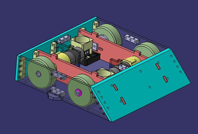
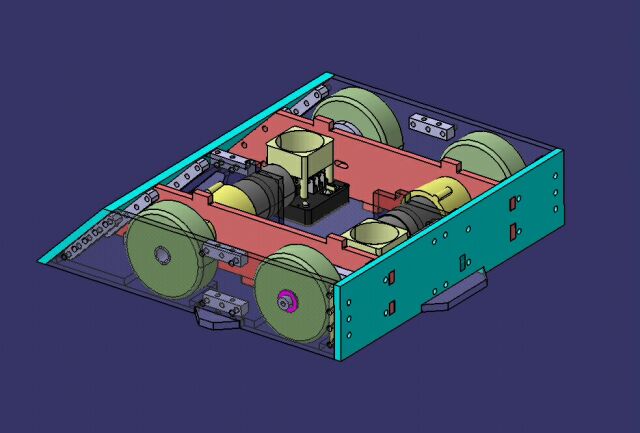
We've been very busy on other things recently but work hasn't completely stopped on CheepShot 3.0. The Harbor Freight motors seem vulnerable to shock damage as we
discovered at RCRAII so I am designing a shock absorbing motor mount design to hopefully much reduce this problem. The mounts are designed so that large loads will cause small movements of the motors
rather than be transmitted right to the magnets etc. inside them. The motor mounts are also designed so that they can fit either the smaller Handiworks type motors or the bigger ones from Harbor
Freight. |
|
|
|
December 3, 2004 |
|
|
|
Work has continued refining the design and preparing the dxf files we will need to have the parts watercut. |
|
|
|
|
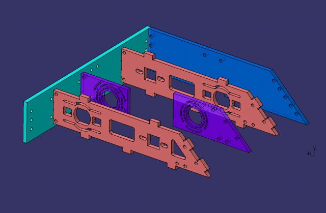
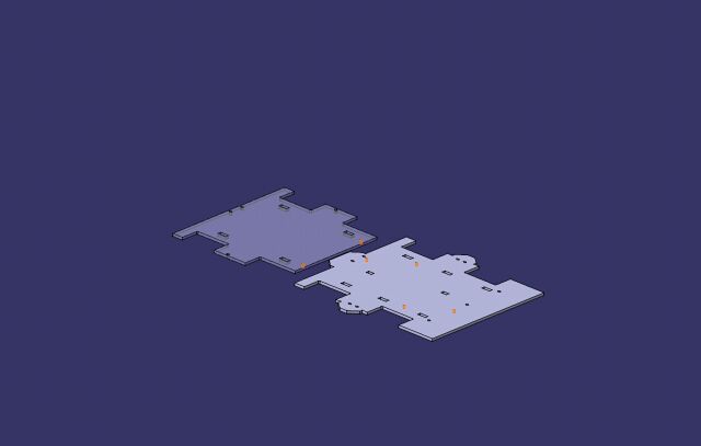
First I created an "assembly" of the top and bottom panels with both lying flat on the same plane and positioned so as to reduce waste material in
the cutting process. |
|
|
|
|
|
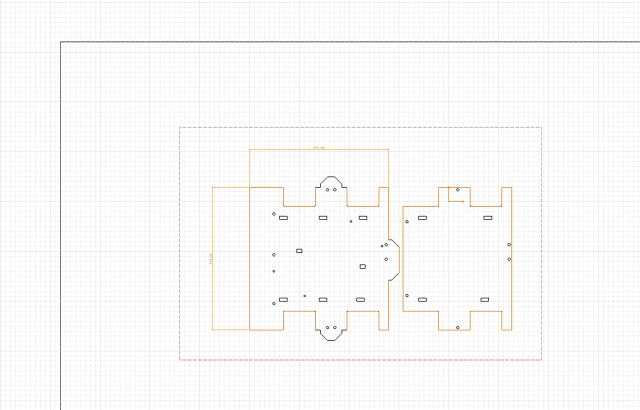
Next I create a 2D drawing of the top view of the assembly. I have added a couple of dimensions to give the watercut folks an idea how big the parts are and
then save it as a .dxf file. |
|
|
|
|
December 6, 2004 |
|
|
|
|
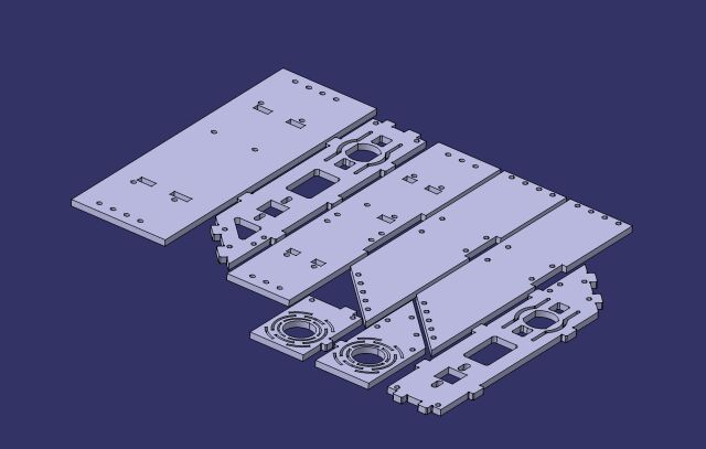
Similarly the panels that make up the rest of the chassis are laid out. |
|
|
|
|
|
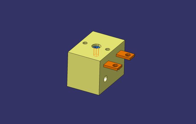
I also modelled the Whyachi MS05 main power switch. I'll use one in CheepShot 3.0 and in Mildly Impolite. The model is in the Solid Models section of the website.
|
|
|
|
|
December 20, 2004 |
|
|
|
I have quotes back for the watercutting and will probably go ahead with getting those parts the first week of next year once one last check of the design is complete.
|
|
|
|
|
|
|
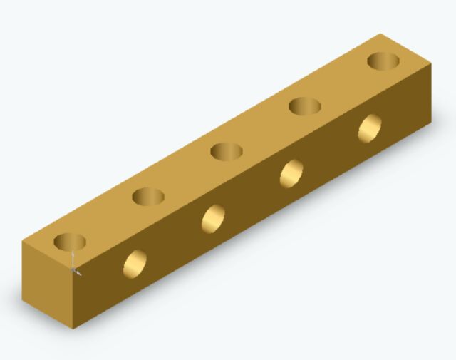
In the meantime I've sent models of the "Nut strip" off to Gregg at
www.cncbotparts.com (no longer in business) for a quote in 2ft lengths. 4ft is enough for building up the bot. Each hole will come ready tapped 10-24. |
|
|
|
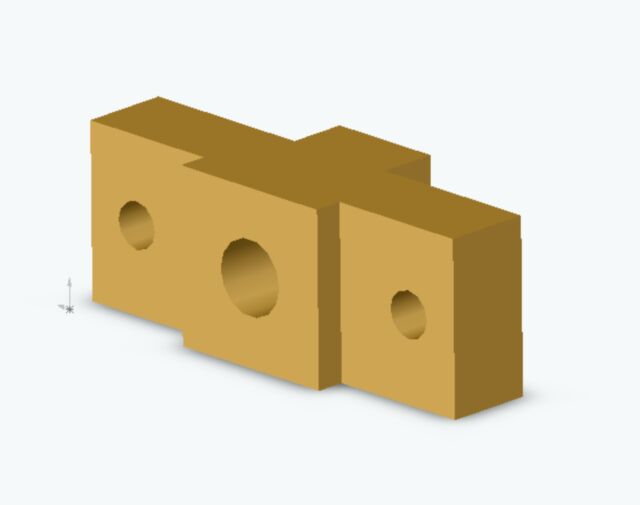
Likewise the blocks that will carry the belt driven axles. The three holes will be tapped 1/4-20 and the centre one is counterbored to fit a 5/16"
shoulder screw. |
|
|
|
|
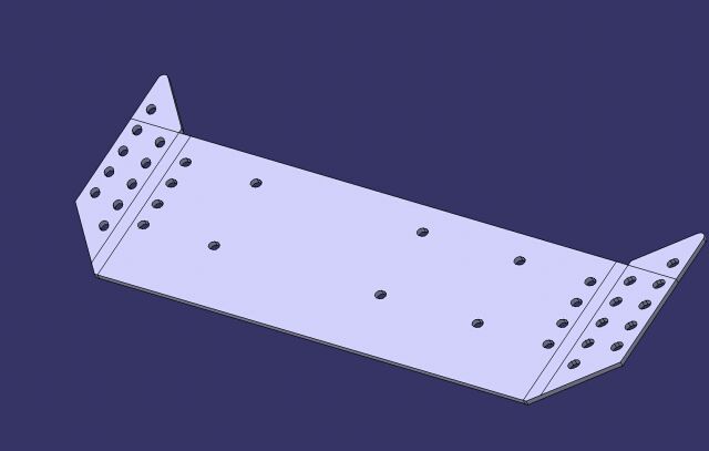
I've also been working on the models for the 1/8" thick overall front and rear corners armour. This is drawn up using a sheet metal function in Catia 5 that lets
you "flatten" it back out so that the profile can be cut. Armour will be either be Hardened S7 or Ti. I'm leaning towards Ti at the moment as it will probably work out cheaper (I hope) and
result in the much loved white sparks when taking on those Spinners!. |
|
|
|
|
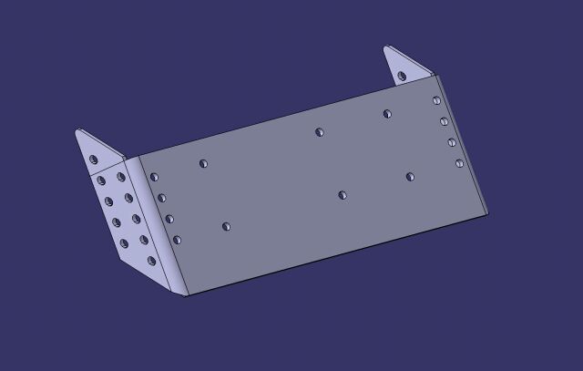
The front armour is similar to that of Xhilarating impaX. It protects the front wedge and the corners. The mounting holes are slotted to allow for errors in
the folding of the sheet metal blank. |
|
|
|
|
|
And the same part "unfolded". This allows a dxf file to be created so that the part can be watercut. |
|
|
|
|
|
Similar folded parts are used for each of the back corners. A model of a 18v 1950AH NiMH pack has been added and the design is virtually complete. |
|
|
|
|
January 5, 2005 |
|
|
|
|
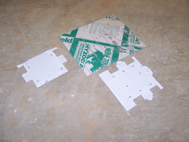
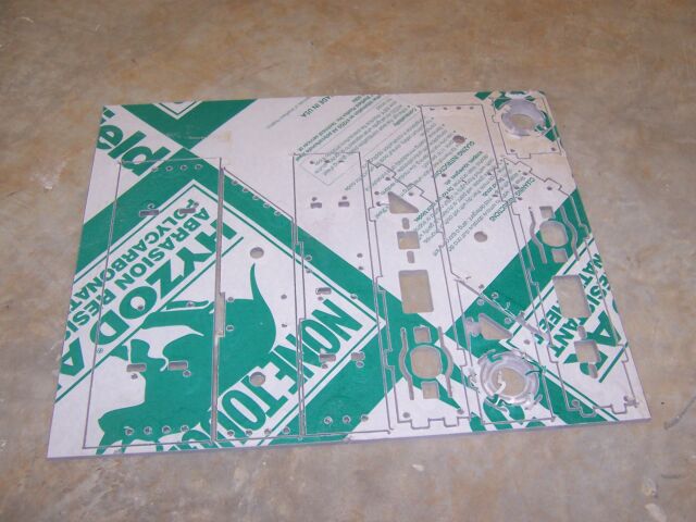
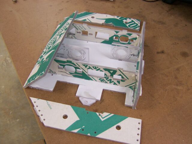
I sent the dxf file to various waterjet companies for quote but again my local company ADR Hydrocut was the most competitive. I picked up the cut panels
today. The 1/4" panels were all held together like a model kit so the small parts wouldn't get lost in the machine. |
|
|
|
|
|
A closer look at the 1/4" thick parts. |
|
|
|
|
|
It took only a few minutes to remove all the panels and trial fit together. The front and rear were a little tight to fit but the rest went together easily.
|
|
|
|
|
|
|
|
|
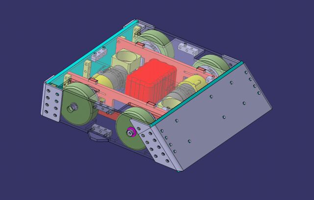
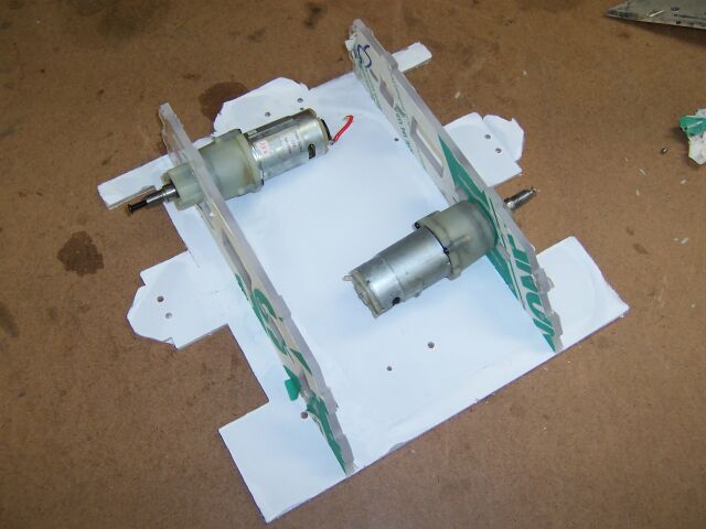
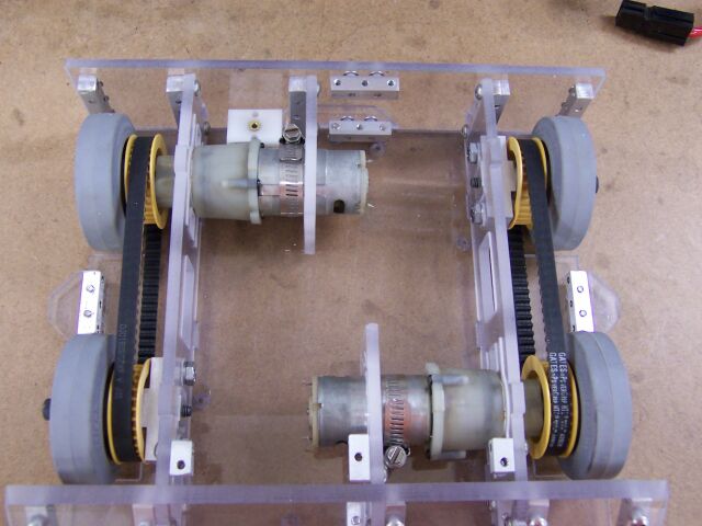
The Harbor Freight Gearboxs fit neatly into their openings. |
|
|
|
The supports for the motors are designed to fit either the handiwork 4.8v or Harbor freight 7.2v motors OR by cutting out the centre "ring" they
will fit the bigger 9.6v 0r 12v Harbor Freight motors. |
|
|
|
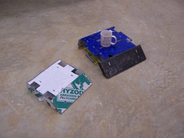
To give you a better idea of the size of the new bot here is CheepShot 3.0 next to its big 30lb brother, Xhilarating impaX. The chassis is remarkably
solid even without any screws holding it together. |
|
|
|
|
The wheels and unique machined parts have been ordered from www.cncbotparts.com
(No longer in business) and the various bearings and screws from www.mcmaster.com
Still need to order the 1950 NiMH battlepack, the sheet of Ti for the armour and the MS05 powerswitch but it looks like it might be ready for Motorama. |
|
|
|
January 17, 2005 |
|
|
|
|
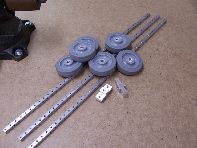
The machined parts have arrived from cncbotparts. They consist of three "Nut Strips", two axle mounts, three standard 3" Colsons and three
3" Colsons with the standard unflanged bushs. I'm only using four wheels but a couple of spares might come in handy one day! |
|
|
|
|
|
|
|
|
|
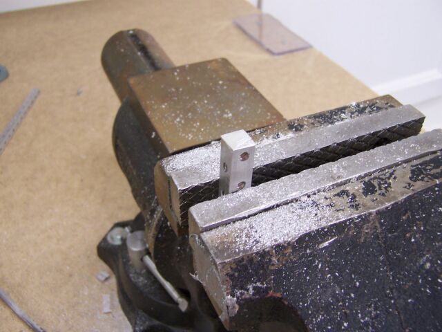
The "Nut Strips" are cut down into shorter "Nut Blocks" and the ends filed to ensure there are no burrs. |
|
|
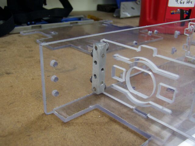
The blocks are then used to hold the various sections of the bot together as shown. The blocks come ready tapped 10-24. I'm using button head screws for
most joints and flat head screws on the top and bottom. |
|
|
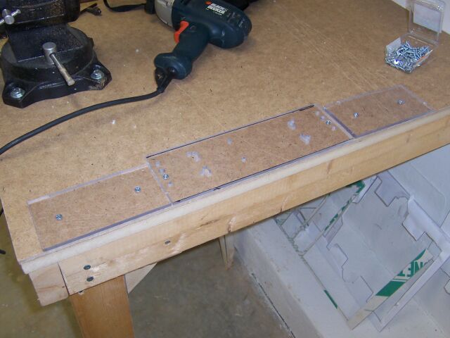
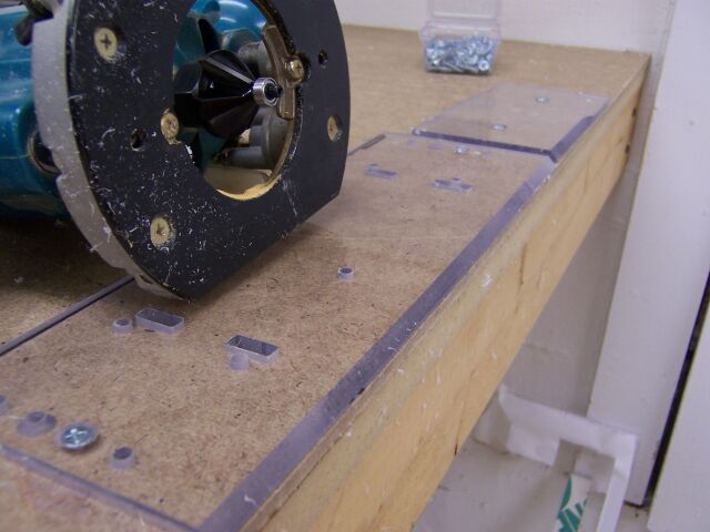
The Front Panel needed to have a 45 degree angle machined int0o the top and bottom edges. I carefully marked which sides needed to be machined and then
screwed the panel to a known straight edge of the bench. Two other scrap panels were added, one on either side of the main panel to support the Router I would use to cut the edge. |
|
|
|
I borrowed a Friends router and bought a 45 degree 9/16" bit. I set the cut at the minimum allowed and took one pass and it didn't take off quite enough
so I eased it out just enough to make a perfect chamfer. |
|
|
|
Trial assembly revealed a few holes missed out in the watercut parts and a few tight fits but it went together pretty easily. I opened up the holes in the
motor mounts to allow the use of the bigger 9.6v motors and these too proved to be a good fit. |
|
|
|
|
|
A trial assembly of the wheels and pulleys showed that I had ordered the wrong length of shoulder screws but that otherwise it should all work OK . I ordered the
new screws today along with a box of #4 self tapping screws that I will use to attach the wheels to the pulleys. |
|
|
|
January 25, 2005 |
|
|
|
|
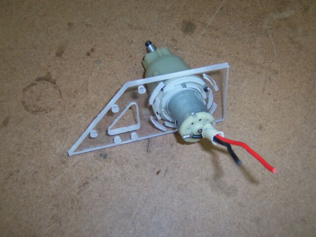
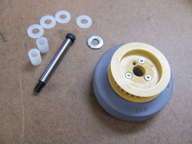
These are the parts that go together to make up the freewheeling wheels. The sprocket was carefully aligned with the standard colson wheel and attached using
three self tapping screws and then a combination of washers and nylon bushes allow it to be positioned correctly along the shoulder screw that acts as a shaft and to spin freely. |
|
|
|
|
|
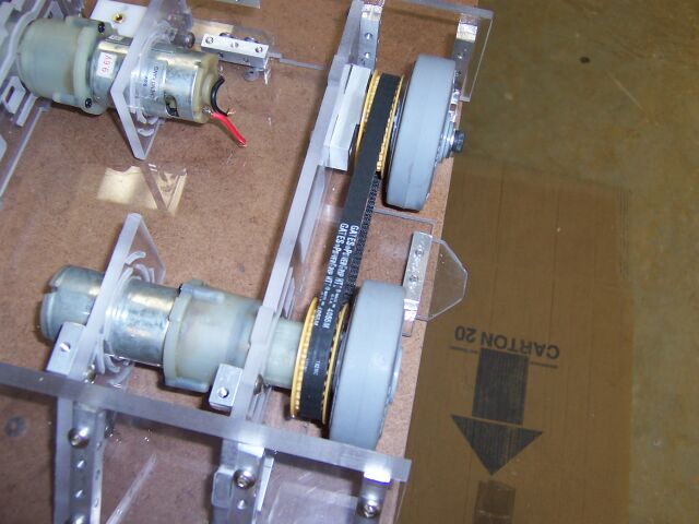
Similarly the Sprockets are mounted to wheel that have the cncbotparts hubs (this was harder as I couldn't use the bushs and shaft to align then for drilling
and screwing together). The wheels and belts were then fitted to the bot. |
|
|
|
|
|
|
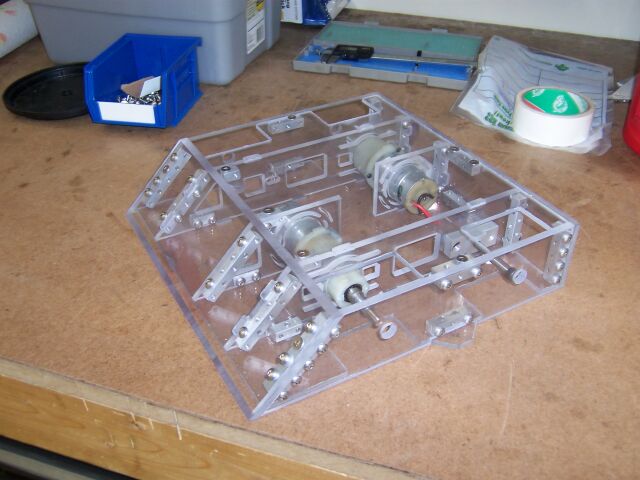
The motors are retained in place using metal hose clips. These stop the mottors sliding back out of their mounts. It was here I noticed that one of the
motors was missing the extra metal "sleeve" they nornally come with. I got a replacement from one of the broken 12v HF motors from CheepShot 2.0 and it fitted perfectly. |
|
|
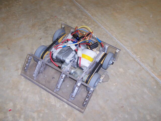
The new 16.8v Battery and the Victor ESCs werenot available yet so I attached up the electrics from CheepShot 2.0 so that we could give it a test drive. I
had expected that it would be a little slow at only 12v but was very pleasantly suprised! See the attached videos to see how well it performs.
Video 1 , Video 2
|
|
|
|
|
|
The bot might turn out to be a bit of a handfull at 16.8v and I might need to limit throttle throws in the TX to keep it drivable. At 12v the Mtroniks and the Motors
kept pretty cool even after about 5 minutes driving. I think that combo would be quite practical in this design giving good speed and power. I'll definitely have them as a backup to the Victors for
Motorama. |
|
|
|
February 1, 2005 |
|
|
|
|
I did not have confidence in my ability to bend Titanium successfully as planned so I decided to make simple flat panels for the front and rear armour. I did
some research on the forums on how to go about this and this proved useful. First thing to do was tracing the outline of the front panel onto the 0.1" Ti I had obtained from Ti Joe. |
|
|
|
|
|
|
I first tried using a fine toothed HSS blade with 3 in 1 oil as a coolant. Using the lowest speed this was mildly successfull cuttting about 6" before
the blade became blunt. I then tried some more expensive Bosch Brand blades with a courser tooth but these made almost no immpression at all on the Ti. Finally I tried the original
fine toothed HSS blades, slow speed and water from a spray bottle (sprayed by my Son) to keep the blade and Ti cool. This worked very well giving good clean cuts and little blade wear.
|
|
|
Drill proved easier. All you need is good sharp bits and slow drill speed (660rpm on my drill press is only just slow enough). As soon as it stops being easy
you need to sharpen the drill bit, luckily I have a "Drill Doctor" sharpener. |
|
|
|
|
|
I countersunk the inner mounting holes. The C'sunk bit was blunt after only six holes. Apparently you want a speed of about 200rpm for c-sinking Ti and my
Drill press won't go that slow. I also tried my big variable speed hand drill but with no more luck even with a new bit. I'm going to see if I can get a friend with a real mill to do it
tomorrow. |
|
|
|
|
|
Similarly the rear panel was marked out and cut. |
|
|
|
|
|
The profile of the rear Ti panel needing a bit of grinding to fit around the rear "anti balancing" extension of the base plate. This was done using
a concrete cutting disk in a hand 4" grinder. This works well and make for some nice sparks! Keep a fire extinguisher handy. |
|
|
|
|
|
The blank rear panel fits very neatly. The spray bottle beside it is the one used when cutting the Ti. |
|
|
|
|
|
I'll be getting the rear hole countersunk and there will be some aluminium or steel reinforcing on the corners (depending on weight). I took the chassis less
esc's and batteries and rear armour to get weighed and it came in at a very slightly over 8lb. so it looks like that is not going to be an issue. |
|
|
|
|
February 13, 2005 |
|
|
|
|
The wiring for the bot is all in 12GA "Wet Noodle". |
|
|
|
|
|
Mark loaned me the Victors from his middle weight "Man O War". The first one I tried only worked in one direction. This might explain some of
his control problems at RCRA II! Luckily he has four and the next two were fine. I do not intend to use the fans as Victors are rated much higher than anything this bot will need. |
|
|
|
|
|
A new 16.8v 1950 NiMH pack from Battlepacks
is used. It took only a little playing around with boosters and settings on the TX to get everything turning the right way at the right time. |
|
|
|
|
Performance is excellent! I have used the dual rating set up (all mixing is done in the TX) to run at 70% power. Full power is just a little too much and would be hard
on the motors and the batteries. It is however available at the flick of a switch on the TX just in case.A short video
of the bot at 70% is here and a second
video showing the pushing power is here. Those are two 13AH Hawkers in that box (over 22lbs!) |
|
|
|
I've still got to get the Ti back from being coutersunk but things are looking good. I also ordered four 12v Harbor freights last week as back ups for the 9.6v ones I'm
using now. They would give more torque at lower RPM but I'm not sure the bot needs it. |
|
|